Unless you plan to live by candle light and bathe in the canal you are going to need electrics and hot water. The two main players when it comes to boat electrics are Victron and Mastervolt, I went for victron as their whole eco-system seems a lot more advanced and customisable (are a lot more guides, examples and advise readily available online). In terms of hot water and heating a calorifier is the only real sensible option, for the diesel heater I chose Webasto over Eberspacher as I liked how they how they have incorporated the use of Heatmiser thermostat controllers.
Table Of Contents
First Fix
Once everything had been ripped out the first thing that was done was to run the cable and pipework. All the hard work put into the diagrams from the design phase really paid off as it was just a case of following the bouncing ball.
Electrics
The biggest plywood sheet you can get is 2440mm x 1220mm, as this is less than the width of the boat the boarding on the ceiling will either be split in the middle or have a gap down both edges. It is within solid uPVC trunking in these side gaps that the lighting wiring is run, flexible corrugated conduit is used for when it traverses the ceiling to the lights final position. It was a bit of a pain getting anything under the batons to the centre of the ceiling but with a lot of perseverance it was manageable without taking down the boards.
The DC (USB, pumps, cigarette lighters) and AC sockets run under the gunwale in separate solid uPVC trunking and then once again go into flexible corrugated conduit to get from gunwale to the sockets final wall position. Running the cables down the walls wasn’t too bad, you just need to try and keep the sockets as close the end of panels as much as possible.
Plumbing
All plumbing is run above the bilge and not concealed in walls so that if there is a leak it is more likely to be noticed (would never know if in the bilge). For the ease of use it was a no brainer to use PVC, it is a lot quicker to fit compared with copper and there is no need to lag the pipes. Water and radiator tails are 15mm, central heating feeds up until the tail should be 22mm. I taped all pipes with blue or red insulation tape every meter and cleated at every 30cm, this is especially true for heating pipes as I have found they become very flexible when the Webasto is running.
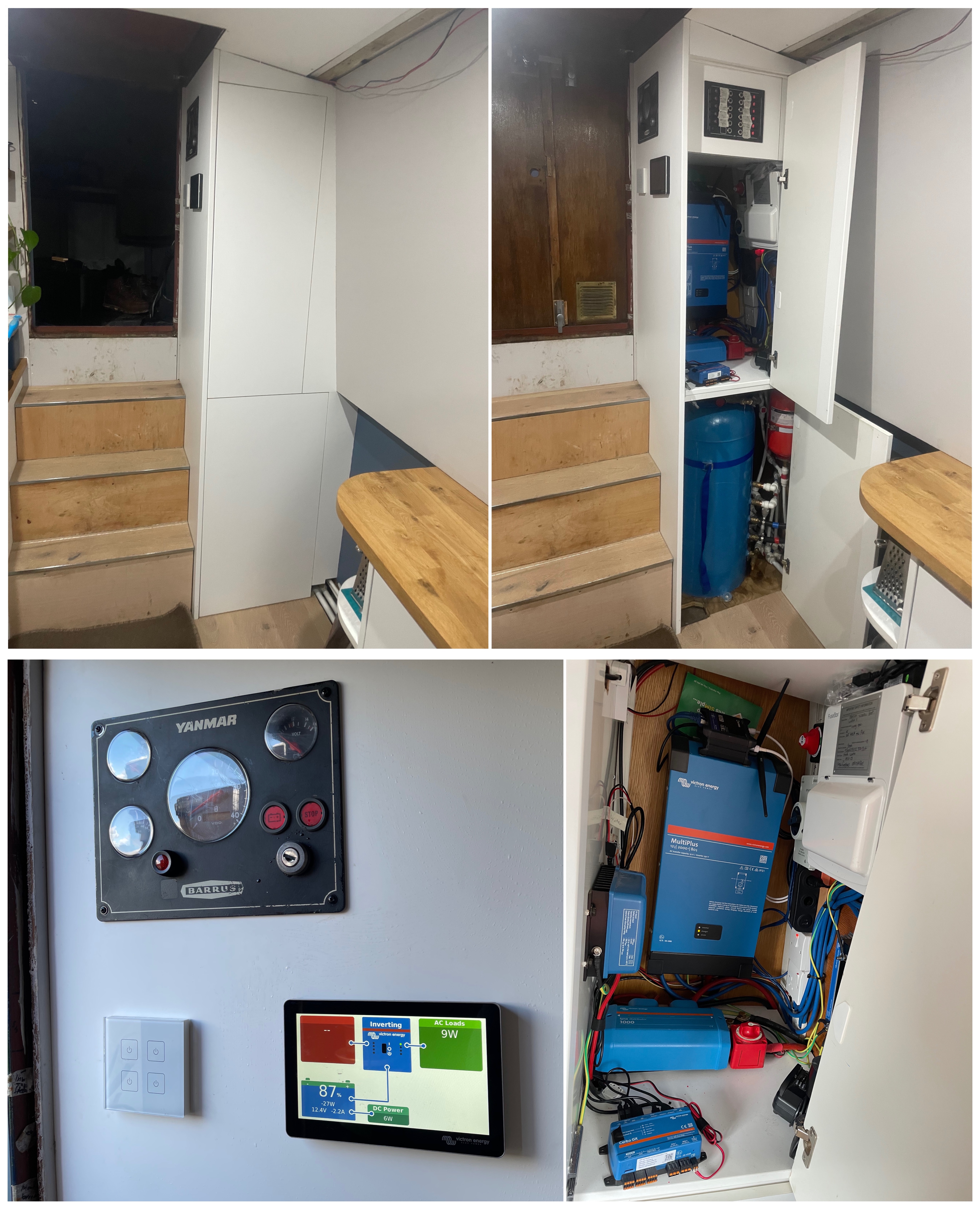
Electric Cupboard
All piping and wiring goes back to the electric cupboard on the port side stern corner. Due to the size of the boat I decided to fit both the electrical components and calorifier in the same cupboard. The inverter and solar charger work optimally at a lower temperature, I am hoping the calorifier insulation and physical separation between cupboards will alleviate the transfer of heat, only time will tell. A computer fan will be fitted to a hole cut in the floor (operated by Cerbo GX based on temperature) to provide ventilation for the electrical components by sucking up cool air from the bilge. The cupboard is made out of melamine MDF with push latches for the doors to keep it minimalistic with no handles.
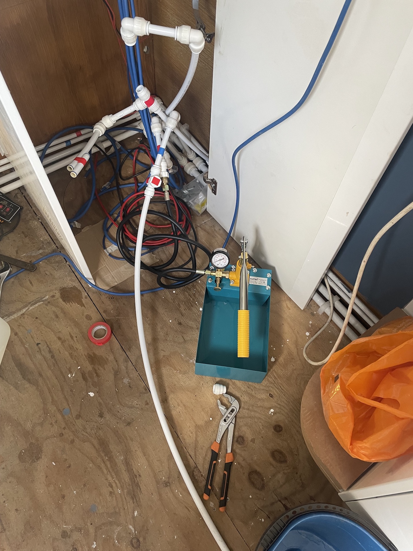
Plumbing
Before the calorifier could be connected up or any kitchen units fixed in place all the pipework needed pressure testing for leaks. All calorifier fixtures were added, tap connectors fitted to water outlets (will eventually take flexible tap tails) and valves put on the radiator tails. I used a water pressure tester to test all piping at 2 bar for 10 minutes and then at 10 bar for 10 minutes as per the JG Speedfit data sheets.
Calorifier
A calorifier is very similar to a hot water cylinder in a house, a copper cylinder full of water that uses coils and/ or an immersion element to heat the water inside it. Choosing the correct calorifier size is a case of finding the middle ground between having sufficient hot water for all your needs against the time it will take to heat it up. I went for a 55 litre vertical twin coil calorifier. It is more efficient to have the primary method (engine) on the bottom coil and secondary method on the top coil (diesel heater) with the hot feed for both of these coming in from the bottom of the coil and exiting through the top of it. Remember to factor into your weight distribution the weight of the calorifier when full, 1 litre weighs 1 kg.
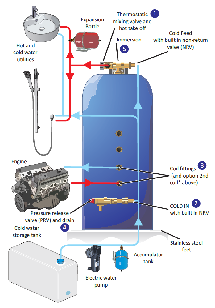
Hot and cold water feeds have cut off taps (cold must be before thermostatic mixer feed) so that the calorifier can be easily isolated and drained. It is coach bolted to the floor at the front and sides with an additional strap in the middle for extra support. The engine water feeds are 13mm so the calorifier 15mm tails needed changing for 13mm tails and 13mm heat resistant rubber heater hose run between the engine and calorifier coil. Once heated the water only keeps warm for a couple of days so I could have probably got away with a smaller calorifier as is only me on the boat.
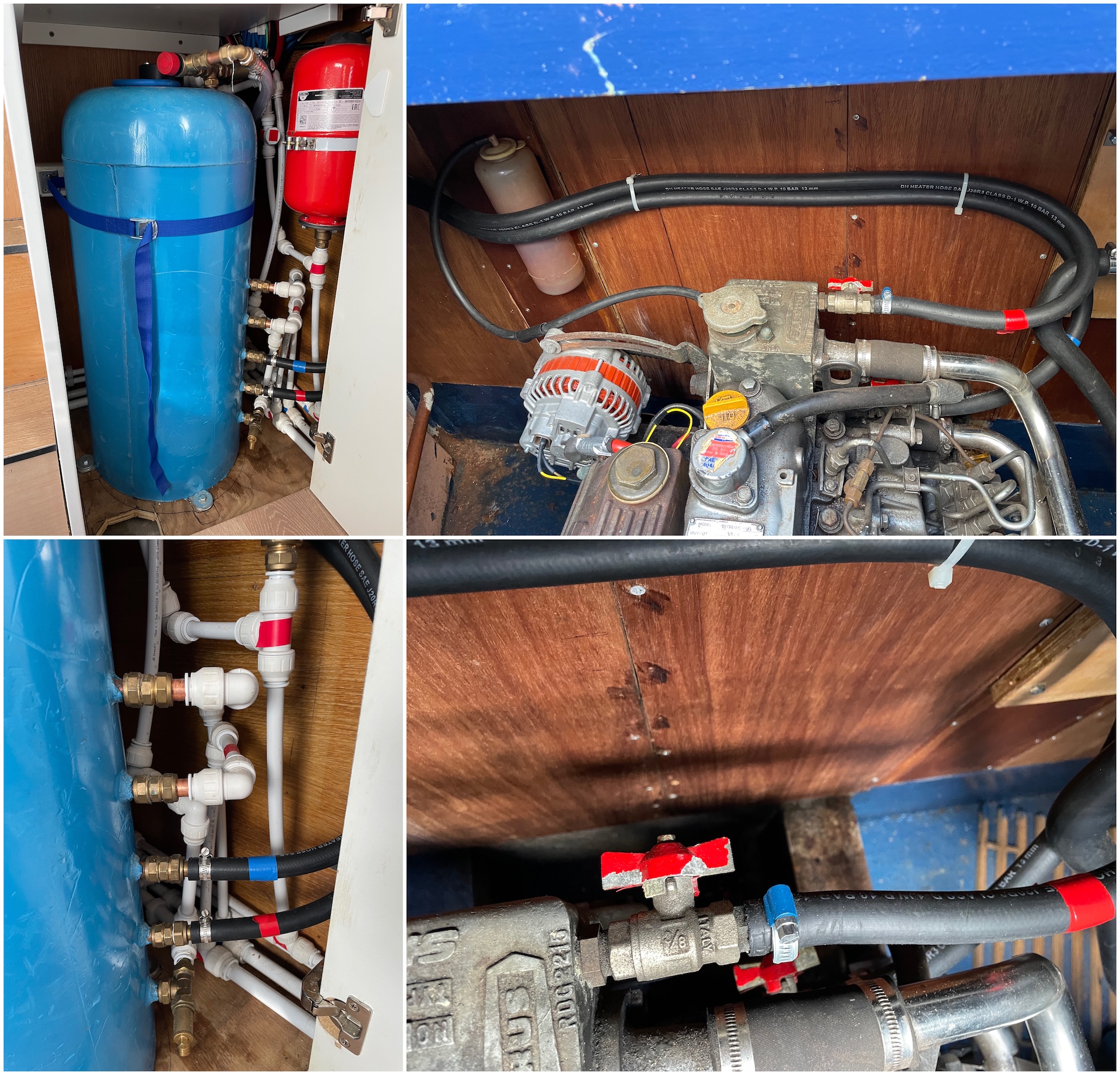
To protect the calorifier from cracking it has a pressure release valve which should ideally vent outside the boat, at the moment this goes into the engine bilge until I get round to drilling a hole in the side of boat. Additionally the hot water feed has a pressurised expansion bottle fitted before any of the taps.
Webasto
The Webasto 5kW diesel heater data sheet states that it should ideally be loaded 10% above its output (so 6kW) to ensure it runs at full load for longer. I think the reason for this is because you don’t want it cycling on and off all the time. For a boat my size with limited space it is not really possible to get that much output. A 600 x 800mm Type 21 double radiator is 1090W, therefore with 2 radiators and a towel rail is about 2500K, I imagine the piping and calorifier will increase that somewhat but it still wont be near 6kW.
I fitted everything from the Webasto Thermo Top EVO Narrowboat Retail Kit except for the fuel and exhaust which was done by Debdale marina (cost £554). Rather than using the fuel line that came with the kit they fitted a fuel cutoff tap and also commisioned the heater as this must be done by a certified Webasto engineer to get your extended warranty. The electrics are connected directly to the batteries so that the heater will always safely warm down (no sudden shut offs), BSS allows this as long as it is fused.
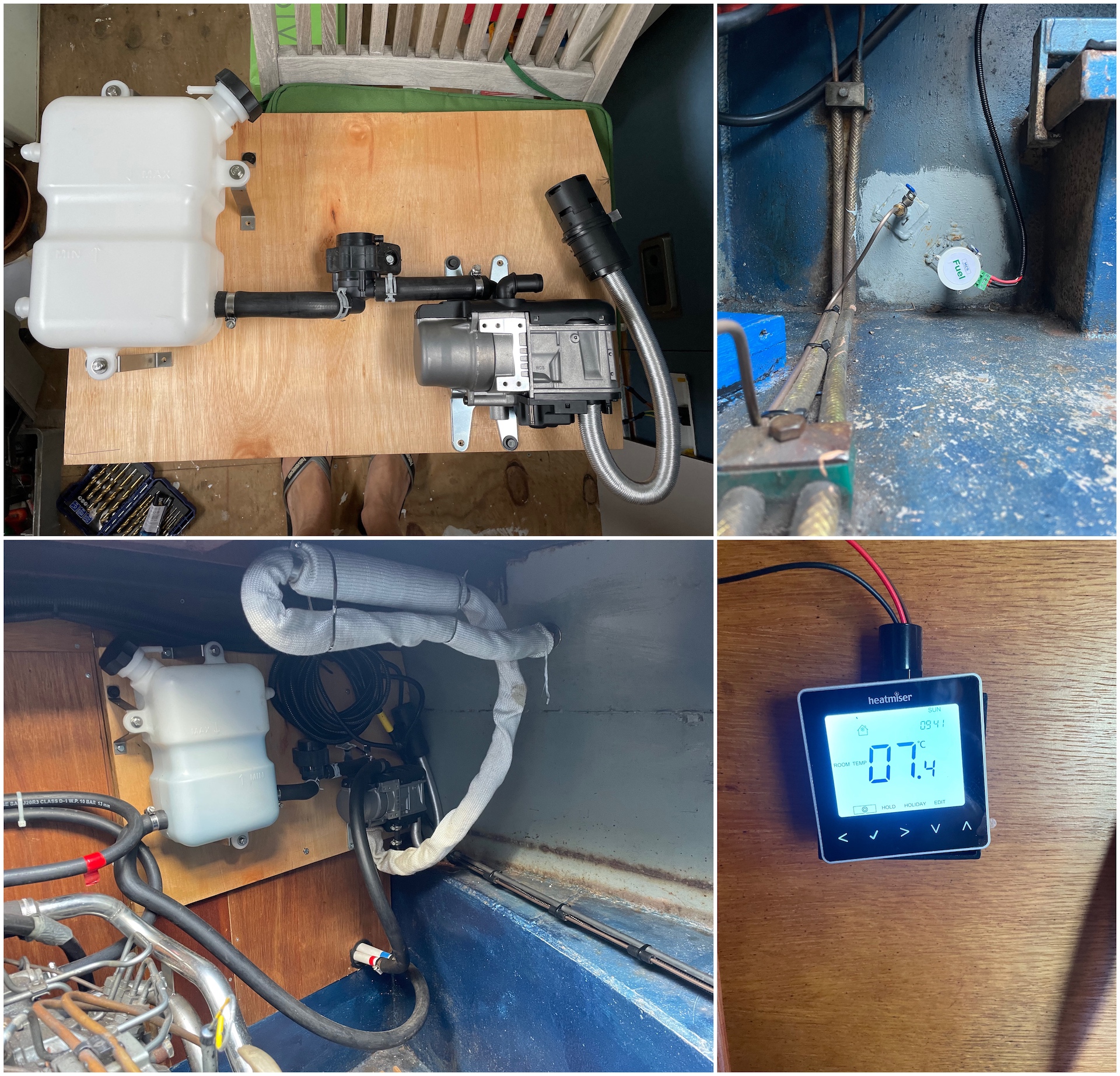
The thermostatic controller is in the bedroom as the galley and lounge would be effected by the stove or cooking, also this way I don’t have far to reach to turn it on from bed. There is a WiFi version of the 230v Heatmiser thermostat, unfortunately there is no 12v equivalent as of yet.
Electrics
Being a continuous cruiser I wont have frequent access to shore power meaning that I have to make efficient use of the batteries (use 12v devices wherever possible and LED lights) as I will have to rely on running the engine (alternator) and the sun (solar panels). I will not have any power hungry devices like a washing machine or microwave, however I will need an inverter of sorts to allow me to have AC sockets and a mains fridge.
As the diagram shows there are lots of different elements involved in the setup, you could mix and match vendors but it seemed sensible to try and get everything by the same vendor for ease of use and compatibility purposes. I chose to go with Victron as their are many reviews and examples of similar types of setups in campervans, boats and off grid housing solutions.
Battery Banks
To comply with BSS both the leisure and starter batteries have isolation switches to cut off anything they supply. The starter battery only has the engine connected, there are no links between the positives of the leisure and starter batteries to prevent accidental draining of the starter battery. The negatives are linked together (via SmarthShunt busbar) to allow the engine to be jump started (by temporarily joining the positives) if the starter battery was to be flat. Other BSS requirements regards batteries are that all batteries are secured in place and most importantly all terminals covered to stop short circuits (a dropped spanner could easily cause a short between the battery positive and negative terminals).
Once you get to cables over 6mm they start to become a lot more expensive and difficult to work with, a hydraulic crimping tool is required to terminate them. Depending on the number of cables required it maybe more economical to buy ready made battery cables.
Leisure Battery Bank
Battery size (power) is measured in Amp-Hours (Ah), so the maximum amount of current (amps) a battery could expend if fully used over an hour. For example a 100Ah battery can expend 100 amps of energy in one hour, or 200 amps during a 30-minute draw. Sizing the battery bank is the middle ground between having enough power to not need to charge and the amount of time it will take to charge. If the bank is so big that the alternator will take days to charge then it is unlikely to ever get a full charge which over time will diminish the batteries health.
The first step in sizing the battery bank is to do a power audit to understand how much power (Ah) I will potential need per-day.
Amps = Watts / Volts (example: 300W / 12V = 25A)
| Device | Power (Amps) | Run time (hour) | Total Ah |
|---|---|---|---|
| Lighting | 1 | 5 | 5 |
| Water pump | 4 | 0.5 | 2 |
| Shower pump | 4 | 0.25 | 1 |
| Fridge | 5 | 6 (estimated total as it cycles on and off) | 30 |
| TV | 4 | 2 | 8 |
| Laptop | 4 | 3 | 12 |
| Phone | 1 | 3 | 3 |
| Router | 0.25 | 24 | 6 |
| Total | 23.25 | 43.75 | 67 |
I will work off 85Ahs per-day to give me room for expansion and miscalculations as this is all theoretical. The other factor to think about is how fast the battery bank can be charged from a non-shore power source, the alternator and solar panels. The alternator is rated at 80A and the max solar I can probably fit on the roof is 500W which would give about 30A, I am assuming the actual efficiency will probably be half these figures.
Before I started this adventure I didn’t realise how limited standard 12v lead acid batteries actually are. You only really get to use 30% of the battery capacity as they shouldn’t be drained past 50% (Depth of Discharge (DoD)) and can take over 12 hours to charge the last 20% (50% to 80% charges quite quick). Lithium batteries are better suited for the usage characteristics on boats as they can be taken down to 80 or 90% DoD and charge a lot quicker, however they are 10 times more expensive to buy and need a specialised alternator (require less resistance to charge).
I have gone for Victron 170Ah AGM supercycle batteries, these are a sealed type of lead acid battery that are a kind of middle ground as are priced in between, can be discharged between 60 and 80% and apparently charge 5 times faster than standard lead acid. The good things about these supercycle batteries is that they offer better performance than other AGM with a smaller footprint. The downside is I didn’t equate the extra weight (47kG compared to 25KG lead acid), for this reason I had to move one to the starboard side. I will start with 2 and plan to add a third later.
| Number of Batteries | Total Ah | 50%Ah/ Time in days | 60%Ah/ Time in days | 80%Ah/ Time in days |
|---|---|---|---|---|
| 2 | 340 | 170/ 2 | 204/ 2.4 | 272/ 3.2 |
| 3 | 510 | 510/ 3 | 306/ 3.6 | 408/ 4.8 |
The positive and negative feeds come from either end of the battery bank as this best distributes the load between all batteries. The length of each feed cable can be different however the length for both the positive and negative cables between batteries in the bank must be exactly the same. Any positive cable connected directly to a battery must have a fuse to protect the cable from burning out. The only things connected directly to battery bank will be the SmartShunt, bilge pump and Webasto, everything else will be behind the battery feed which has a 300A fuse.

Power Inputs
There are 3 power sources that can be used to charge the batteries, solar and shore power are better than the alternator for maintaining the longevity of the battery as they both use 3 stage charging:
- Bulk (constant current): The charger slowly increases the charge voltage to maintain a constant charge current to the battery (as many amps as it can supply or battery can take), this is what brings the battery upto 80%. Continues until the battery voltage reaches the specified absorption voltage (differs for battery brands and types)
- Absorption: (constant voltage): The charger maintains a constant voltage (absorption voltage) and the charge current decreases over time, this is the trickle charge that takes the battery up close to its 100%. As time goes on the number of amps drop off as the battery gets fuller since the charger requires less amps to maintain the battery at the specified voltage. This stage ends when the number of amps drops to nearly nothing or after a specified time (set as time limited in charger settings)
- Float: (constant voltage): The charger now just holds the battery at a lower specified voltage (float voltage) trickling the lowest number of amps that it can in to the battery to maintain the float voltage (is not really charging it anymore)
An alternator will charge the battery as fast as it can or the battery will let it, whichever is lower. The amount of current that goes into the battery will naturally decrease as the battery charges, the voltage increases as it nears 80% and eventually becomes constant (usually between 14.4 and 14.6v). The battery bank is full when the amps is constantly lower than 2% or 3% of the battery bank Ah capacity, voltage is not good sign of full charge. My assumption is that this behavior sounds similar to the bulk and absorption stages of a 3 stage charger, although the actual absorption voltage value is what the alternator regulator is set to (max voltage it can go to). A SmartShunt and Cerbo GX give you visibility into this charging behavior as they record the voltage and amps through the batteries whilst charging. This canalworld forum has a lot of good info about charging.
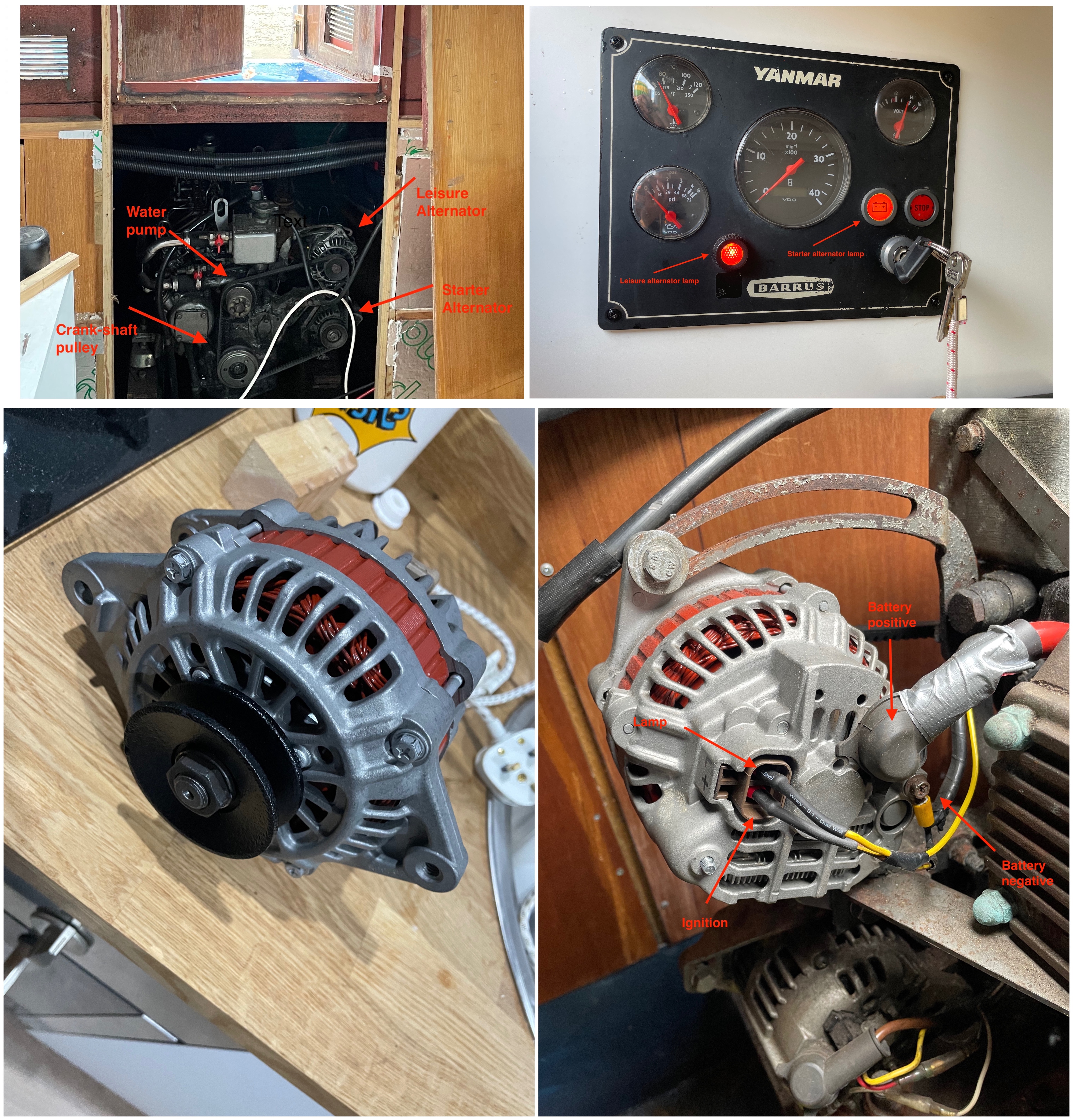
Alternators
The engine has a starter (40A) and leisure alternator (80A) both off the same V-belt. This is not ideal, normally the starter alternator, engine water pump and crank shaft pulley are on a V-belt and the leisure alternator on a second pulley using a flat belt. The downside of them being on the one belt is that the belt is more likely to slip and wear, I just need to be a little more cautious and regularly check the tension.
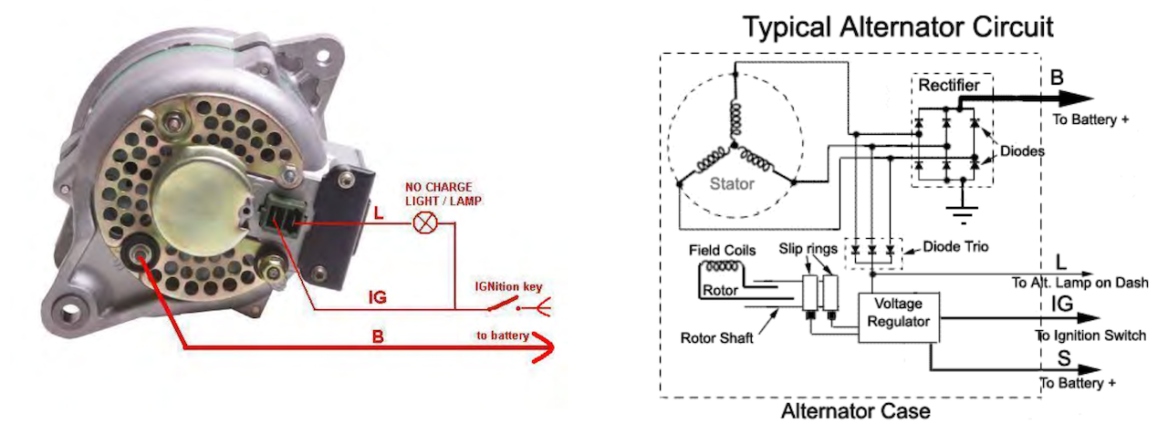
Each alternator has 4 terminals, positive and negative for charging the battery, ignition (from engine ignition) and lamp (goes through bulb on dashboard). From my understanding when you turn the ignition key part-way the lamp comes on to show the alternator is working (voltage on alternator ignition terminal but not lamp terminal), then when the engine is started it goes out due to a diode changing current to positive over this lamp circuit (voltage on alternator lamp terminal) and starts charging the battery.
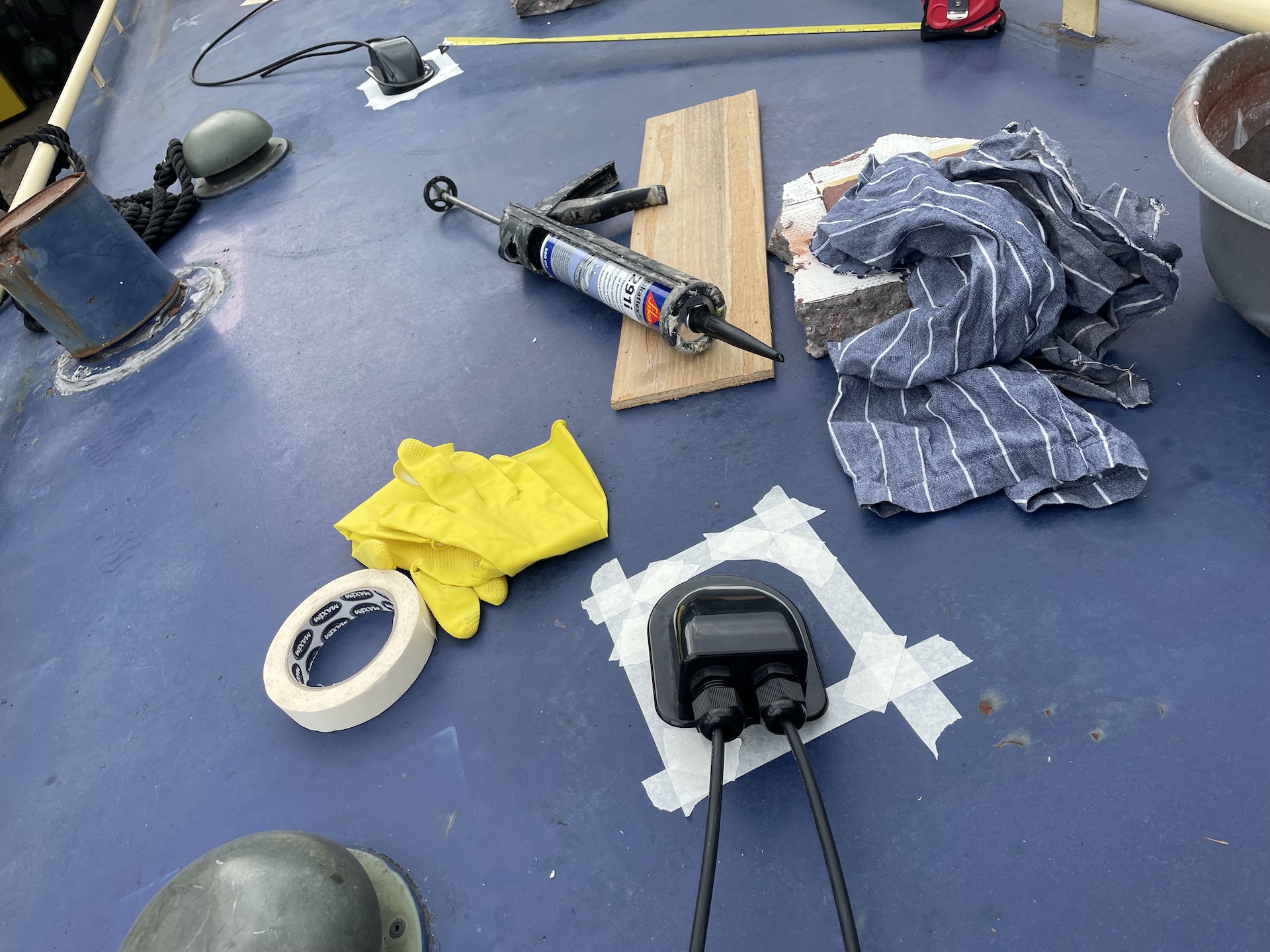
Solar
Everything except for the panels has been pre-installed, these will be fitted in mid April. Panels use standard MC4 connectors, I ran toughened 6mm cable which has a protective outer sheaf as it will be out in the elements. This was drilled through the roof with protective covers stuck on with sikaflex. On a sunny day solar panels can generate a lot of voltage so a 32A isolation switch is required so that they can be isolated.
Initially I am going to have two 200W Monocrystalline panels wired in series (daisy chained), this means the voltages are added but the amps are not (this is a good post to explain the pros and cons of series vs parallel). I didn’t want the whole width of the roof taken up so these panels give me the best power for the size, it also allows enough room in the middle to add another panel if needed (can just insert middle of the daisy chain).
The job of the Maximum Power Point Tracking (MPPT) solar controller is to take the output voltage of the solar panel and reduce it to the level that the battery requires in a way that maximises the amount of charge delivered by the solar array. There is a victron tool for working out the MPPT size required, in the MPPT model number the first number is the maximum PV open circuit voltage (Voc, the input voltage from solar panels) and second number the maximum charge current (output amps into the batteries). Based on 2 x 200 watt (2 for day1, may add extra 130W day2) the recommendation is a SmartSolar MPPT 100/30 (max input 100V, max output 30A).
Input (Voc): 23.6 + 23.6 + 22.32 = 69.52
Output (Isc): 10.8 + 10.8 + 7.54 = 29.14
Shoreline
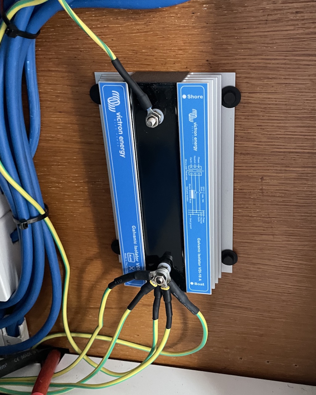
The shore power feed is protected by a 32A 2-pole RCBO (MCB and RCCB in one) that effectively shuts off all mains power to the boat (could have got away with 16A). When plugged into shore power the boat is actually connected via the mains earth to all other boats in the marina also on shore power. This is a perfect condition for galvanic corrosion which if left unchecked can cause serious pitting on the hull. To prevent this a galvanic isolater is fitted that isolates the boat from the shore power earth whilst still allowing the earth to trip the shore RCD in the event of a fault. The earth from the shore power goes to one side with all earths on the boat (including boat chassis earth) going to the other side.
Victron Core
The core elements of the electric setup are the Victron MultiPlus combi (inverter and battery charger in one), MPPT solar charger, SmartShunt battery monitor, voltage tank monitor and Cerbo GX. The Cerbo GX is the brains of the operation as it is the central place for configuration, data collation, sharing and telemetry data display.
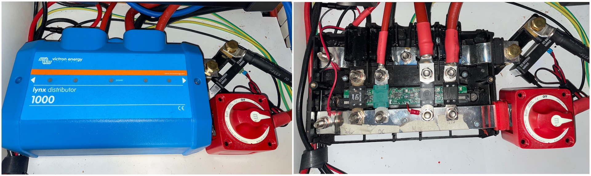
Lynx Distributer
Everything that drains or charges the battery bank needs to be connected to it in some way via a sufficiently sized fuse. This is where the Lynx Distributer comes in, it is effectively a negative and positive busbar with fuses. The fuse status lights are designed to be powered by the Lynx Smart BMS which also allows the fuses to be monitored remotely, as I don’t have this the lights power supply lead is doctored to be powered from the busbars. An alternative option is to get a cheaper Lynx Power In and customise it to take fuses.
| Fuse Size | Connection |
|---|---|
| 300A | MultiPlus |
| 125A | DC breaker panel |
| 80A | Alternator and negative for engine bay |
| 40A | MPPT solar controller |
| 3.15A | Cerbo GX (not housed in lynx, is an inline slow burn fuse) |
There must be an isolation switch for all battery banks, the starter battery isolation switch is in the engine bay and the leisure battery bank 300A isolation switch attached directly to the Lynx Distributer. The switch has an M10 sized connection so the positive busbar hole needed widening from M8, the same applied for the negative busbar as the SmartShunt connects to the negative busbar in the same manner (an M10 bolt).
SmartShunt
Due to the limitations of 12v batteries (actual usable capacity) it is really important to know what level the battery is at as under or overcharging will reduce its capacity and lifecycle (only have an finite number of charging cycles). There is no easy way to be 100% sure of the battery level from external monitoring, however a SmartShunt can at least give an indication (State of Charge) of what it thinks is left in the battery. The SoC is not determined by voltage but rather by amp usage over a specific time period based on the current in/out of the battery (how much energy you have pulled from them). If the correct battery bank size is not set, are old batteries (so cant get the full Ahs) or the battery wasn’t charged fully through the correct length of absorption (not a good start point as doesn’t have the full Ahs) then this figure will be distorted and inaccurate.
If the battery monitor does not perform a regular synchronisation (reset SoC to 100%) over time the SoC will start to drift. Synchronisation is an automatic process that occurs when the SmartShunt thinks the battery has been fully charged based on the following 3 conditions:
- The battery voltage is above the charged voltage (float voltage)
- The current into the battery is less than the tail current (a percentage of the battery capacity)
- The above 2 conditions are true for a certain amount of time (charged detection time)
In theory the SoC shouldn’t really drift if the batteries are regularly charged with solar or shore power, however if charging with the alternator it is probably best to also keep an eye on the battery voltage to make sure they are not being discharged too low. Unfortunately judging battery levels based on voltage is tricky as the battery has to be in it’s true resting state for some time. The voltage will fluctuate as high draw appliances are used and rise once stopped. There are some generic AGM voltage tables like the one shown below, however I cant find one specific to my supercycle batteries so it will be a case of creating my own baselines based on usage.
| SOC | Open-Circuit Voltage (after 2 hours of inactivity) | Discharge Condition 0.1C (discharge @10Amps) |
|---|---|---|
| 100% | 12.85V | 12.50V |
| 80% | - | 12.25V |
| 75% | 12.55V | - |
| 60% | - | 12.05V |
| 50% | 12.25V | 11.95V |
| 40% | - | 11.75V |
| 25% | 11.95V | - |
| 20% | - | 11.35V |
| 0% | 11.65V | 10.8v |
The SmarthShunt monitors the battery bank temperature to optimise battery charging (need additional temperature sensor) and this data displayed and shared by the Cerbo GX with the MultiPlus and MPPT. All negative connections must go to the southside of the shunt, only the shunt itself should be connected to the negative side of the battery bank. As there are things in the engine bay that must connect to the battery bank (Webasto, alternator, bilge pump) the SmartShunt negative side had to be extend onto a 300A negative busbar in the engine bay.
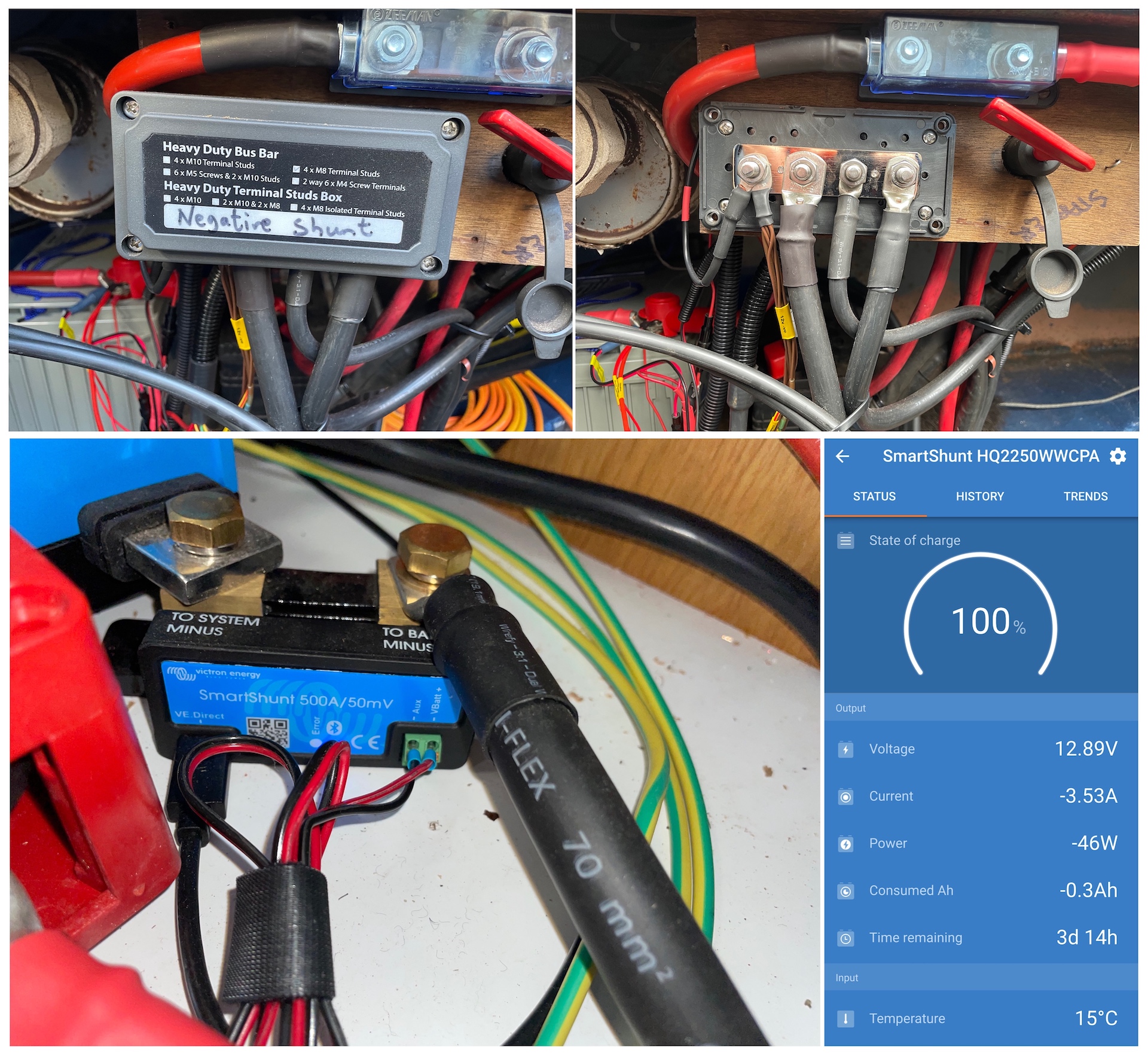
The time time-to-go value of the SmartShunt is not the time until the battery will get to 0%, it is the time till it gets to the level you want to discharge your batteries to (set as the discharge floor). This obviously fluctuates when drawing heavy loads and rises once these stop and battery goes closer to its nominal resting state.
MultiPlus Combi
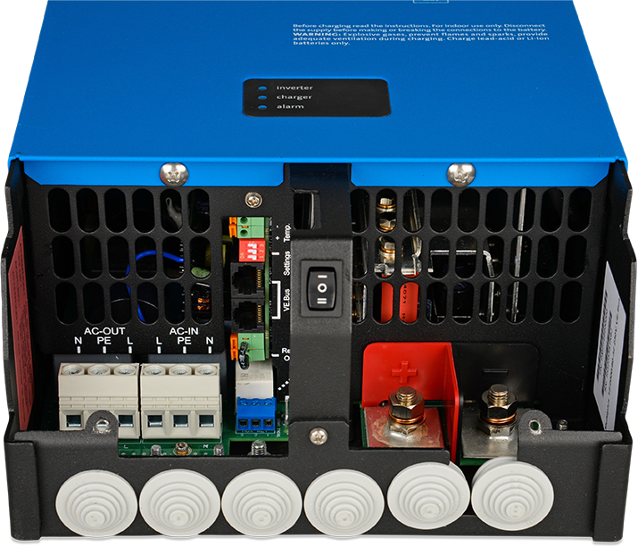
A MultiPlus combi is an all in one appliance that can generate DC from AC when connected to a shore power (a battery charger) and from DC to AC when not (an inverter). They are sized based on watts (inverter power) and amps (charger power), I went for the the MultiPlus 2000W/80A as the battery bank will not be massive and I don’t plan to have many power hungry AC devices. The wattage is actually irrelevant when hooked up to shore power as the MultiPlus bypasses the leisure batteries and inverter to power the appliances directly from the mains.
It can be left plugged in on shore power all the time without damaging the batteries as the charger has a float stage that will keep the batteries in tip top condition and act like a mains powered battery to run all of the 12V services. The MultiPlus recommended battery bank capacity is 350-1000 Ahs, my initial battery bank size of 340 is just below this but shouldn’t be an issue as I don’t plan to use the MultiPlus to its full capacity.
The connections and setup are pretty straightforward, AC in (shore power), AC out (AC on the boat) and battery bank connections. I am not using the dedicated battery temperature sensor that came with it as it shares the SmartsShunts temperature sensor. The charging settings such as float voltage, absorption voltage and time are preset to Gel/AGM batteries so didn’t need changing. As it doesn’t have bluetooth a MK3 USB dongle is required to connect via its ethernet port to configure it. It doesn’t have a magnitude of settings, I don’t think I had to change anything.
Cerbo GX
The Cerbo GX is best described as the brains of the operations, it is hard wired to all other victron equipment allowing them to share information between themselves (SoC, battery temperature, etc) as well as collating and displaying this information on a touch screen. The amount of configuration that can be changed is dependant on the type of equipment that is connected. It is powered directly off the Lynx distributer and the touch screen gets its power from the Cerbo GX. It also has 2 programable relays allowing you to make the Cerbo GX perform an action (turn on power to a device) based on a certain condition (for example a temperature change).
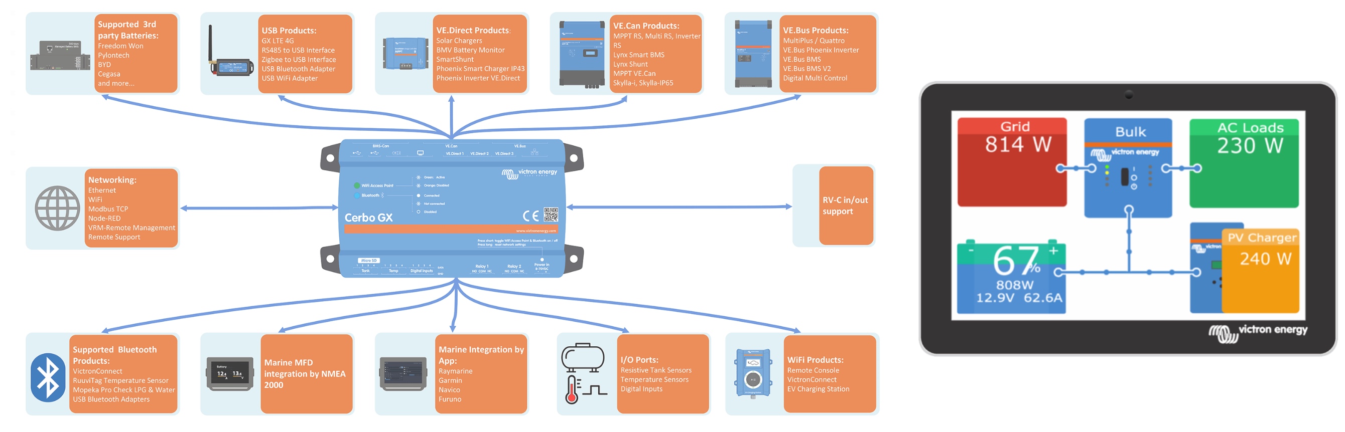
The Cerbo GX talks with the Victron VRM cloud portal via WiFi allowing all of the information it holds to be remotely accessible in the portal with the ability to make certain configurational changes and look at historical graphs and trends.
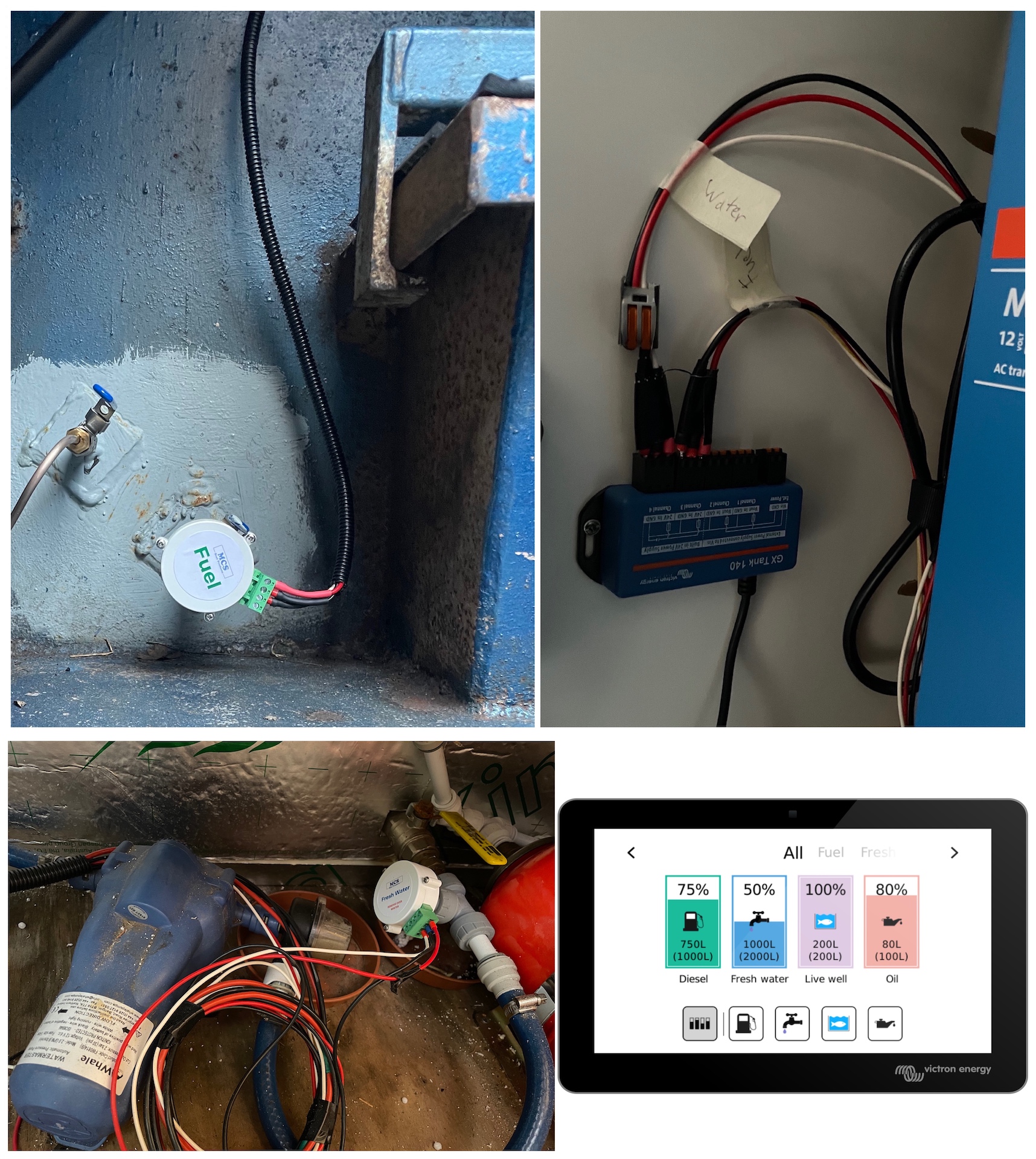
Tank Sensors
The only way to measure the water and diesel levels on the boat was with a stick, I brought this into the 20th century by fitting a water and fuel gauge. Both are of similar stature, voltage gauges that relay back to the Cerbo GX (via a GX Tank 140 voltage monitor as Cerbo GX only has builtin amp monitors) a voltage between 0 and 10v depending on how full they are (guess is based on liquid pressure). The water gauge is connected inline via a T between the water tank and pump whilst for the fuel gauge I had a tap installed at the bottom of the fuel tank with a 1⁄4” thread that the gauge screws into. Each gauge has 3 connections back to the tank monitor, positive and negative for 12/24v power and a sensor signal.
The tank configurations are done via the Cerbo GX, you can select the type (for display symbol) and the tank size. In the display under the tank configuration it shows the sensor value which is the realtime voltage. Once the tank has been filled the gauge has to be calibrated so that voltage only just gets to 10v, you can temporarily lower the averaging time to 1 second to make it more sensitive whilst calibrating.
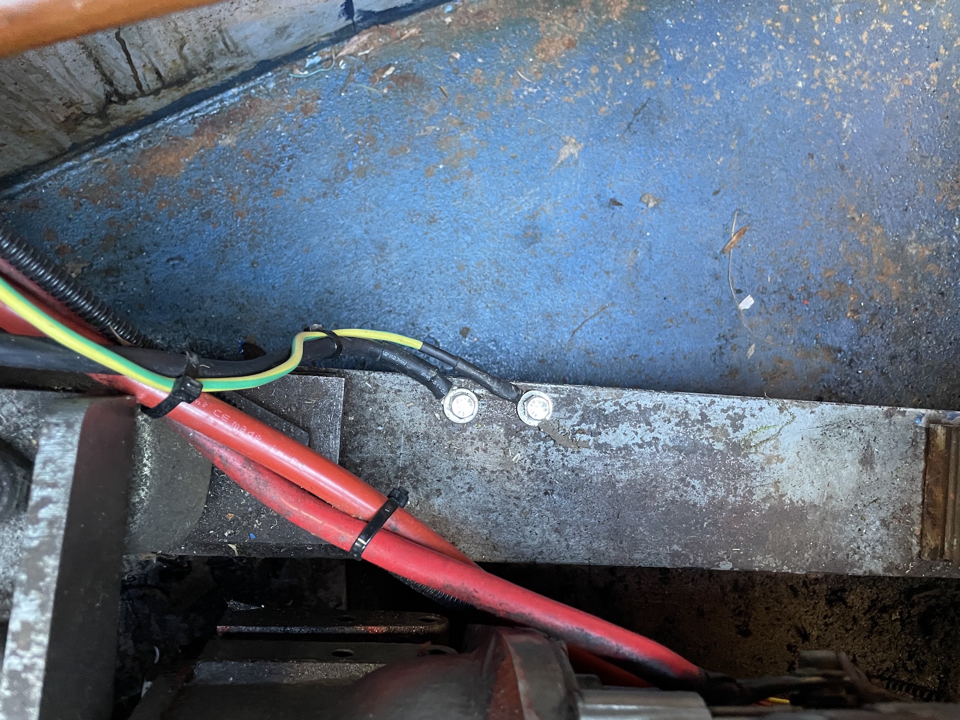
Power outputs
For BSS compliance both the AC and DC environments need to be earthed to the boat chassis. The AC came from the southside of the galvanic isolater and the DC was a negative feed from the SmartShunt busbar in the engine bay.
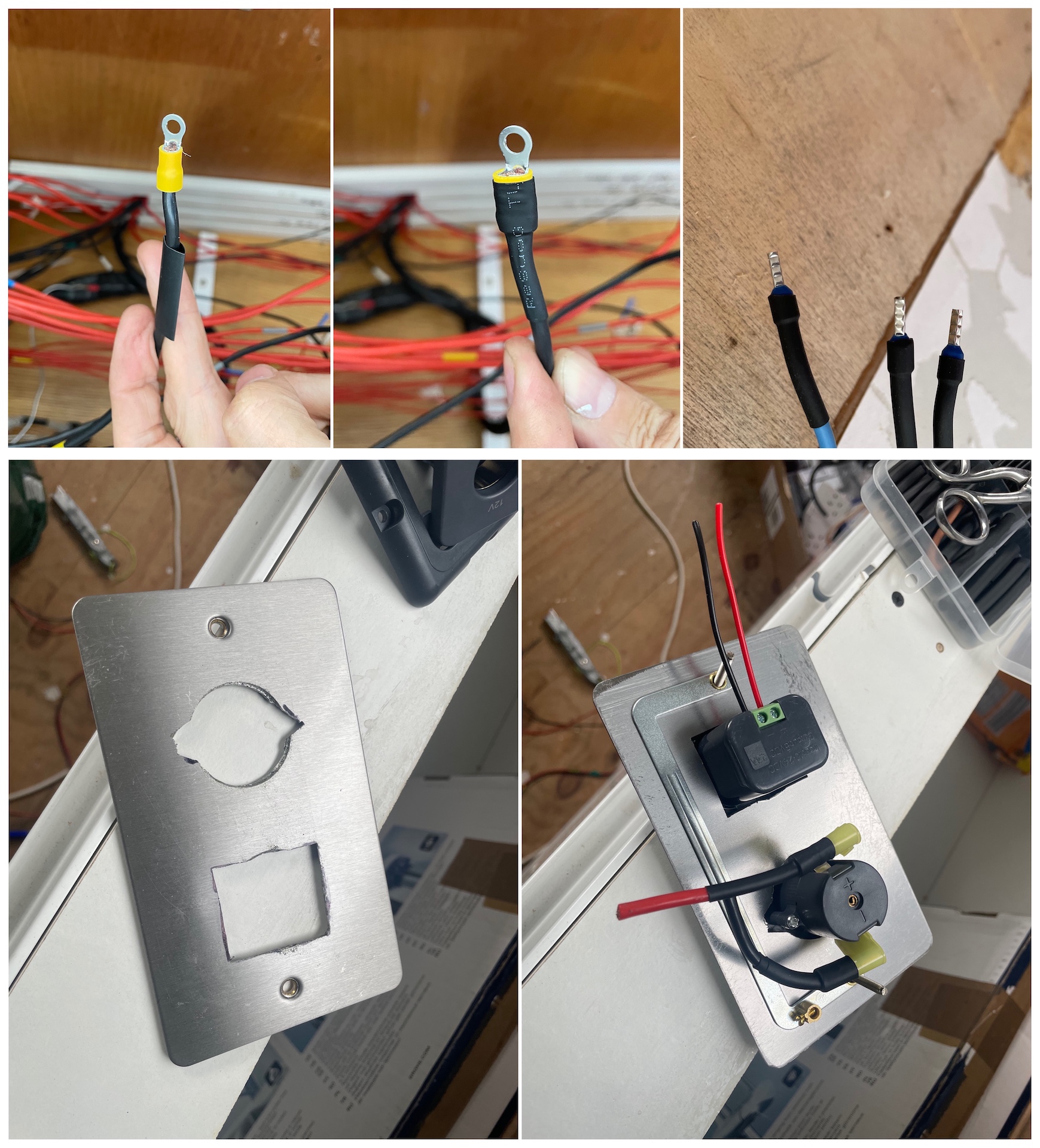
12v DC
It seems a bit archaic that in this day and age everything regarding 12v still uses crimp connectors, you would think that by now someone could have come up with something better. Ideally the crimps should have heat shrink wraps to reenforce the connection, as I got to doing larger cables I found shrink wraps with adhesive which were a lot better than the none adhesive ones I had been using. I wasn’t going to go and redo everything so in the end used the adhesive heat shrinks for the more important heavy duty connections such as batteries and Lynx Distributer connections.
If I had know how difficult it would be to fit the 12v cigarette lighter sockets I wouldn’t have done so many, I started off using AC sockets back boxes with a metal faceplate but in some cases due to wall depth had to just fit them direct with no back box or surface mount if not in plain view.
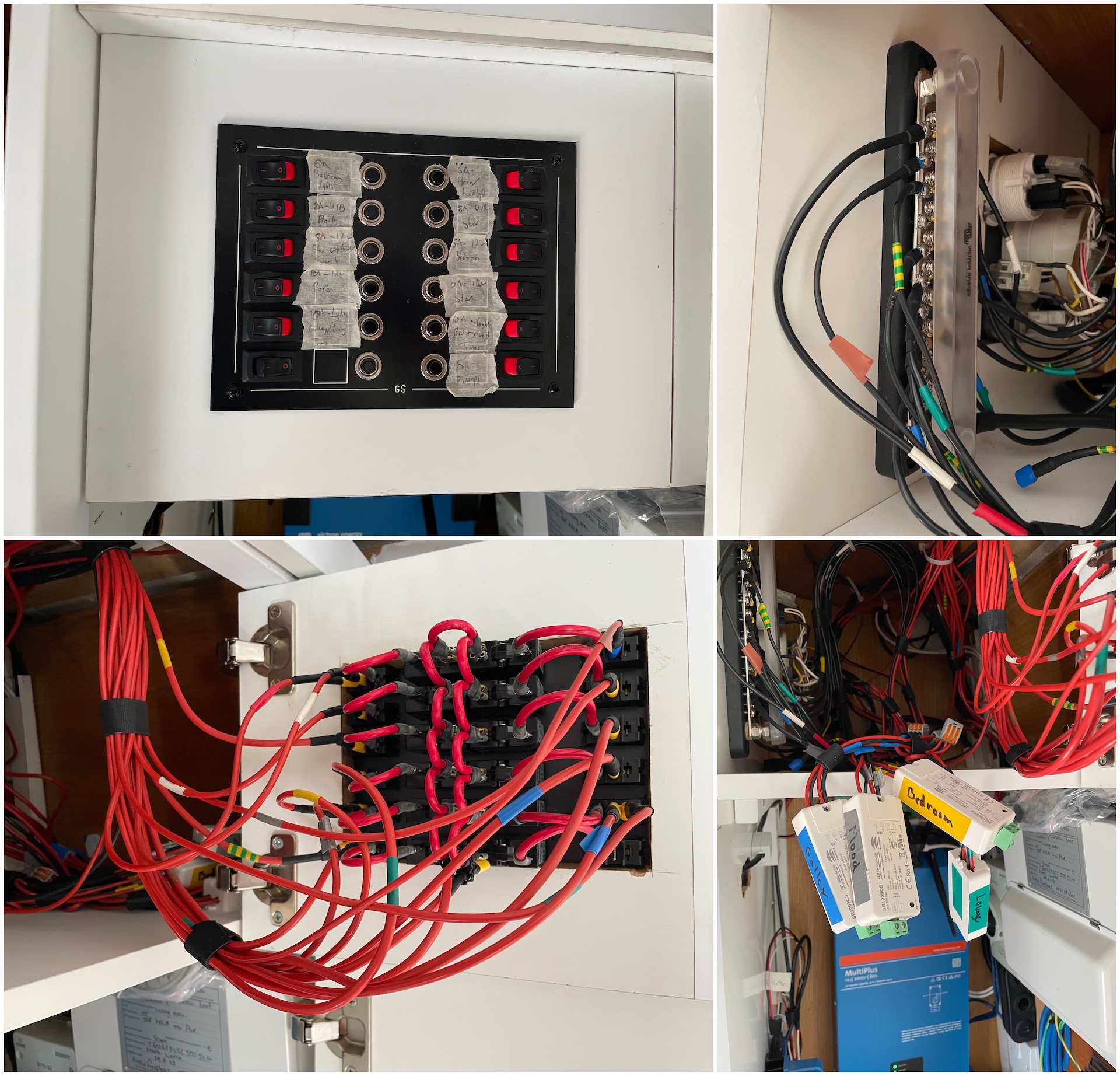
The negative side for all 12 volt internal components terminate on a 20 screw 150A busbar, the positive sockets and pumps on a 12 way circuit breaker panel and the positive lighting circuits on RF receivers (which in turn terminate on the DC board). The positive and negative feeds come from the Lynx Distributer with a 275A isolation switch on the positive supply to allow for all internal the 12v systems to be turned off.
| Circuit breaker size | Number of breakers | Usage |
|---|---|---|
| 6A | 2 | front light & horn, bathroom lights |
| 8A | 4 | USB port-side, USB starboard-side, 12v electric cupboard, 12v bedroom |
| 10A | 4 | 12v port-side, 12v starboard-side, galley & lounge lights, bedroom & mood lights |
| 15A | 2 | pumps (water pump, shower pump), spare |
230v Mains
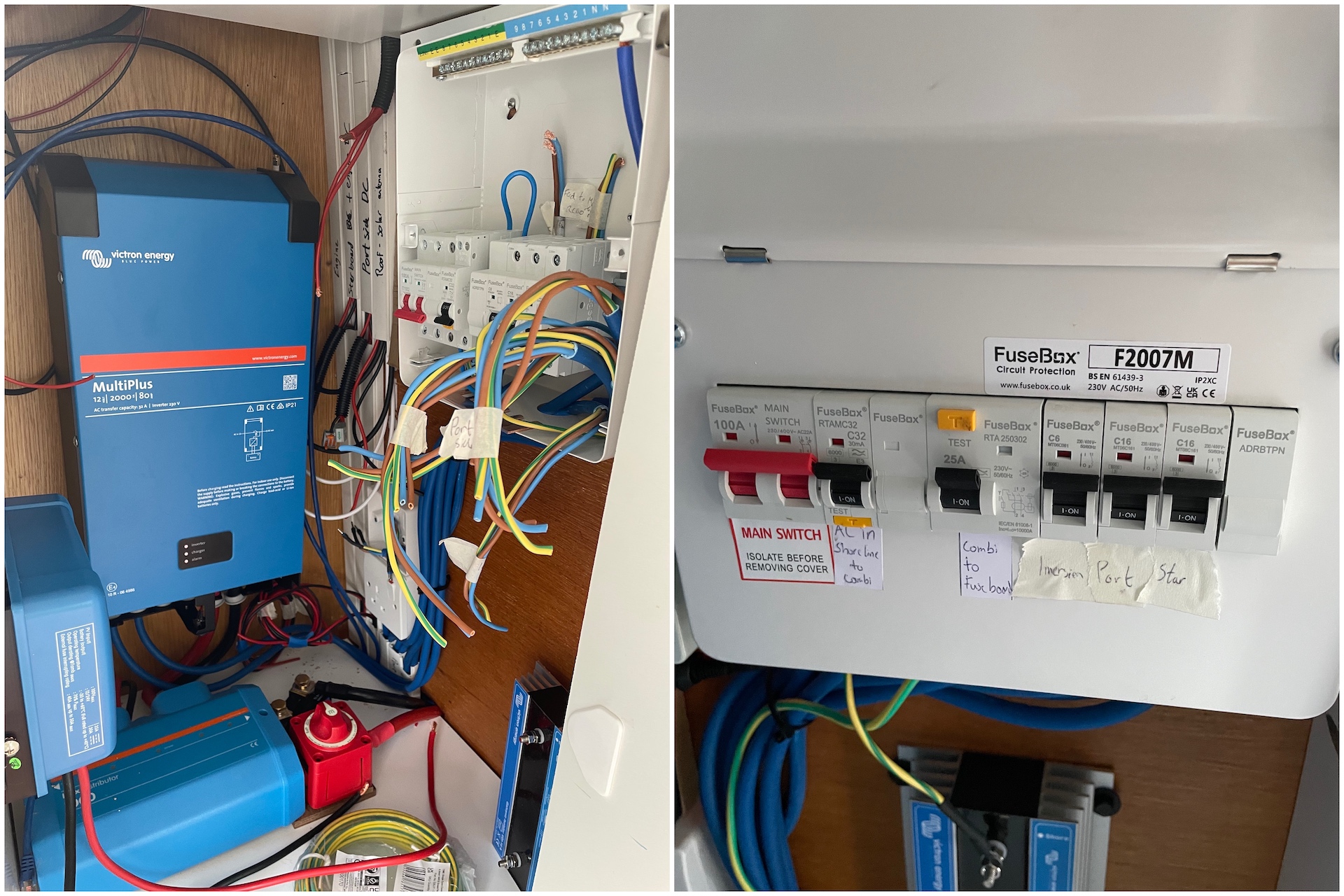
The 230v mains feed comes into the MultiPlus via the 32A RCBO and the MultiPlus output terminates on a 25A RCD. From here there are two 16A MCBs and one 6A MCB which are all housed along with the RCBO in a metal 7way consumer unit. These days housing regulations stipulate that these must be metal, I couldn’t find a definite answer on whether this is also the case for boats so went ahead with metal as a precaution.
As the RCBO is just 1 module it made sense to house everything in the one consumer unit to save space. RCD and RCB0 on a boat must be a 2-pole as it must break both live and neutral, the MCBs can be 1-pole and only break live. The shore power earth doesn’t terminate in the consumer unit, it goes to northside the galvanic isolator with the southside of the GI coming back and being the actual earth for the consumer unit.
| Type | Size | Pole | Input | Output | Usage |
|---|---|---|---|---|---|
| Switch | N/A | 2 | Shoreline | RCBO | Where the shoreline feed terminates |
| RCBO | 32A | 2 | Switch | MultiPlus input | Passes the shoreline feed into MultiPlus |
| RCD | 16A | 2 | MultiPlus output | MCBs | Brings MultiPlus output into consumer unit for MCBs |
| MCD | 16A | 1 | RCD (consumer unit positive busbar) | Port-side ring main | All sockets on port-side |
| MCD | 16A | 1 | RCD (consumer unit positive busbar) | Starboard-side ring main | All sockets on starboard-side |
| MCD | 6A | 1 | RCD (consumer unit positive busbar) | Calorifier | Immersion heater of calorifier (via 3A switch) |
Internet
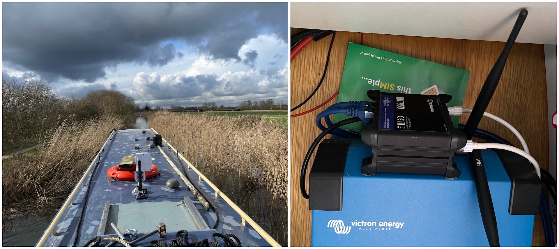
A narrowboat is basically a big steel box so is not great for mobile phone reception. Ideally I wanted Starlink but costs are too high at the moment so the more economical solution is to use mobile as 4G and 5G data plans are quiet reasonably priced. A 5G Poynting antenna (4G backward compatible) is fitted on the roof using a magnetic pole and connects back to a Teltonika RUT950 4G router in the electricity cupboard. On a bigger boat you would probably want it in the middle of the boat but for my boat is fine being situated where it is.
This router model is now EoL (but not EoS) so you can pick them up quite cheap on eBay. They can be run off a 12volt power supply which makes it ideal for keeping the battery bank usage down as the router will be on all the time. Is probably not that much of interest to general boat people but these routers have an abundance of network features such as BGP, OSPF, PBR, VPN, load balancing, dual SIM WAN fallback and firewall.
The downside of this setup is that there will obviously be coverage blackholes in certain areas. The mobile networks aren’t really designed for multiple devices competing for bandwidth, this isn’t as much as a problem for one person living a simple life on a boat.