This post goes through how to configure MPLS VPN on the service-side of a Cisco SD-WAN edge device, so the south-side towards non-SD-WAN devices. What I am trying to achieve is to advertise the differing SD-WAN VPN (VRF, why Cisco have to call these VPNs beats me) prefixes to a core switch (using a ASR in the lab) directly connected to the SD-WAN router. This could be accomplished using per-VRF interfaces (or sub-interfaces) and BGP peerings, but a neater solution is to pass all the routing information over one the BGP MPLS VPNv4 peering.
Cisco Documentation
So lets start with the 17.2.1r release notes on the matter.
The Cisco IOS XE SD-WAN devices support Multiprotocol Label Switching (MPLS) to enable multiple protocol environment. MPLS offers an extremely scalable, protocol agnostic, data-carrying mechanism that transfers data packets with assigned labels across the network through virtual links. Extensions of the BGP protocol can be used to manage an MPLS path. The Cisco IOS XE SD-WAN devices also have the capability of BGP MPLS VPN Option B.
The multiple service VPNs use inter autonomous system (AS) BGP labeled path to forward the traffic, that in turn helps scale the service side VPNs with less control plane signaling. MPLS interface is supported only in global VRF.
Feature Name |
Release Information | Description |
|---|---|---|
| MPLS-BGP Support on the Service Side | Cisco IOS XE Release 17.2.1r | This features allows you to enable support on Multiprotocol Label Switching (MPLS). Multiple Service VPNs use inter autonomous system (AS) BGP labelled path to forward the traffic, which in turn helps scaling the service side VPNs with less control plane signaling. Label distribution for a given VPN routing and forwarding (VRF) instance on a given device can be handled by Border Gateway Protocol (BGP). |
As you can see the information is not really the greatest, the biggest point I took from this is ‘MPLS interface is supported only in global VRF’ which means it has to be configured under the transport VPN as service-side VPNs are not in the global VRF.
MPLS Options
Is probably worth a quick recap of MPLS VPN before moving on to the configuration. There are three options to establish an Inter-AS:
- Option A - Back-to-Back VRFs: There is no end-to-end LSP (label switched path) as although LSP may be used for Intra-AS connections to devices within a site (behind the edge router), packets are sent unlabelled between sites (Inter-AS) on a per-VRF basis using IGP or IPv4 BGP.
- Option B - BGP IPv4 and VPNv4: The link between edge routers has no IGP or LDP configuration as instead the inter-AS connection uses the IPv4 and VPNv4 BGP address-families to generate and exchange labels in the BGP updates between neighbors.
- Option C - BGP VPNv4 with LDP: Between edge routers LDP is used to form neighbors and communicate label information whilst IGP is used advertise loopbacks which then in turn form the eBGP VPNv4 peerings to exchange the prefix information.
Both option B and C use the BGP VPNv4 BGP address family to get the routing information between sites and to tell the remote router what label value to use. Option B is exchanging these labels using an IPv4 BGP address-family peering rather than LDP. This blog by Daniel Dib offers a really clear explanation of the differences between the options.
Configure the SD-WAN Edge device
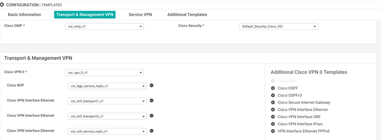
Although the SD-WAN MPLS VPN BGP peering is going to carry service-side traffic the MPLS interface must be in the global routing table which means the interface and BGP feature templates are added under the transport and management VPN section of the device template.
-
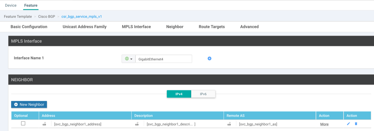
Create a VPN Interface Ethernet template: The configuration of the feature template is no different to any other service-side interface. tunnel mode should remain disabled as although it is associated under the transport VPN it is not actually a transport interface.
-
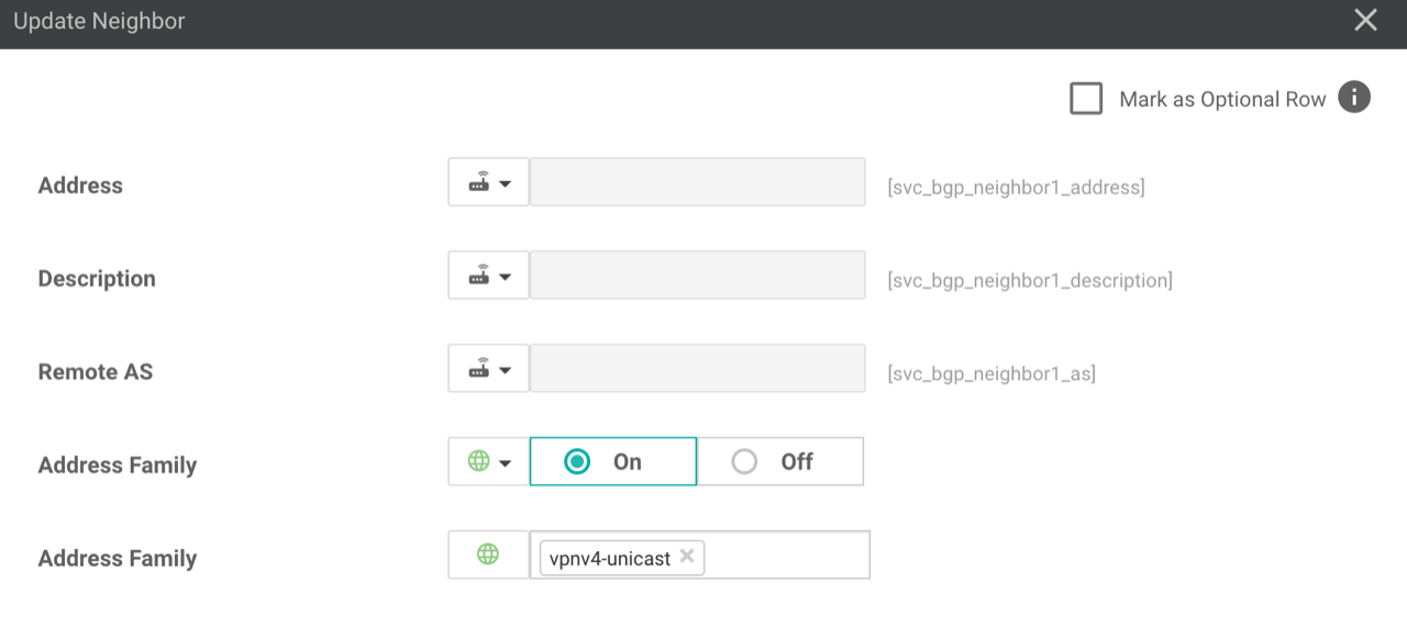
Create a BGP template: Within the template define the MPLS interface that the BGP peering will be established over (created in step 1) aswell as the BGP neighbour.

The address family is VPNv4-unicast, all other settings can be left as default. Do not try and set any redistribution or RD/RT within the template, this is done under the VRF’s BGP address family.

- Update the device template: Add the interface and BGP template to the transport and management VPN section of the device template.

For any old school CLI people like myself, the resulting configuration that this creates is as follows:
interfaceGigabitEthernet4
description MPLS VPN connection
no shutdown
arp timeout 1200
mpls bgp forwarding
ip address192.168.20.2 255.255.255.240
no ip redirects
ip mtu 1500
load-interval 30
mtu 1500!
mpls label mode all-vrfs protocol bgp-vpnv4 per-vrf
mpls label mode all-vrfs protocol bgp-vpnv6 per-vrf
mpls label range 100000 1048575 static 16 99!
router bgp65106
bgp router-id192.168.20.2
neighbor192.168.20.1 remote-as65106
neighbor192.168.20.1 descriptionDC0-ASR-LAB01 MPLS BGP session
neighbor192.168.20.1 ebgp-multihop 1
neighbor192.168.20.1 send-community both
address-family vpnv4 unicast
neighbor192.168.20.1 activate
neighbor192.168.20.1 send-community both
At this point the BGP peering will be up but nothing learnt or advertised until the service-side VPN is added.
-
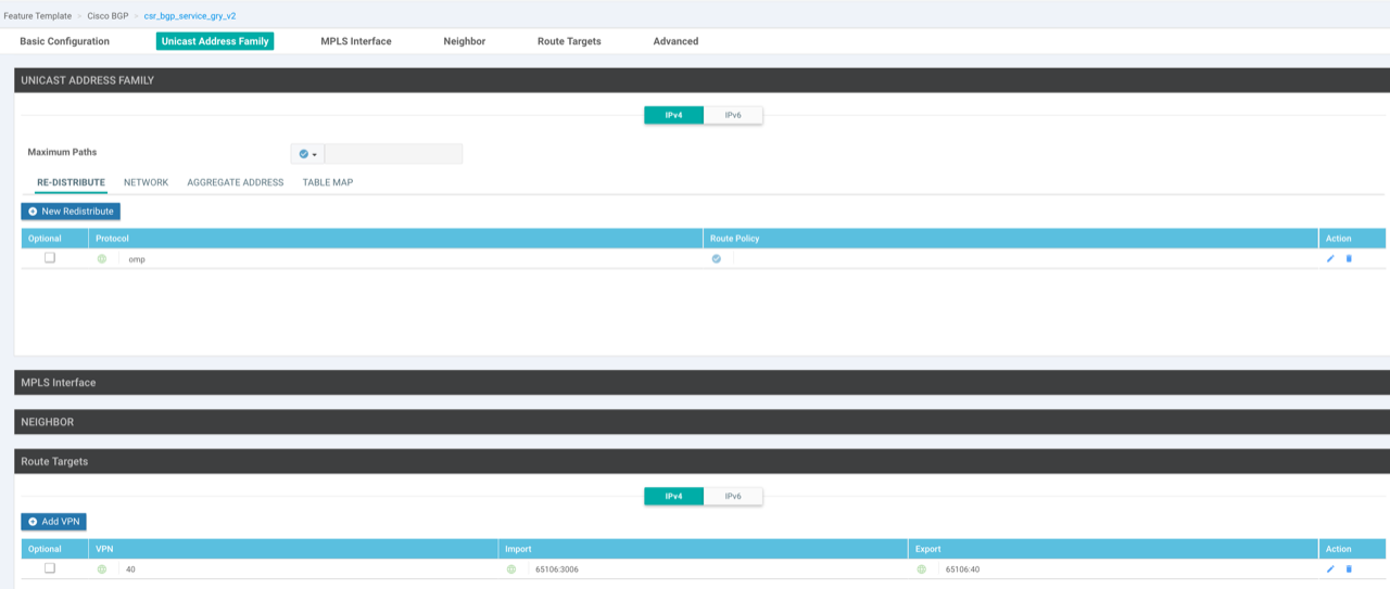
Add service-side VPN templates: Create a VPN template for the VRF, a VPN Interface Ethernet template for the loopback (used for testing) and a VRF specific BGP template (address-family). The BGP template advertises the loopback interface, redistributes OMP routes from this VPN into BGP and set the import route-target to import prefixes learnt from the remote router.

-
Apply service-side VPN templates: Add the BGP and loopback interface feature templates as sub-templates under the service-side VPN within the device template.

The resulting configuration of this is as follows:
omp
address-family ipv4 vrf40
advertise bgp!
vrf definition40
descriptionGRY
rd1:40
address-family ipv4
route-target export65106:40
route-target import65106:3006
route-target import65106:40 !
interfaceLoopback10
no shutdown
arp timeout 1200
vrf forwarding40
ip address1.1.1.1 255.255.255.255
no ip redirects
ip mtu 1500!
router bgp65106
address-family ipv4 unicast vrf40
bgp router-id192.255.255.81
network1.1.1.1 mask 255.255.255.255
redistribute omp
Configure neighboring device
For the purpose of this demo I am using a Cisco ASR1002X.
- Configure connecting interface: The interface that connects to the SD-WAN router is in the global routing table and must have mpls bgp forwarding enabled. I am only using sub-interface on port-channel as this equipment is part of a bigger lab, this could be a normal interface.
interfacePort-channel11.3020
encapsulation dot1Q3020
ip address192.168.20.1 255.255.255.240
mpls bgp forwarding
- Add the VRF: The RT import values should match the RT export values on the SD-WAN router.
vrf definitionGRY
rd192.168.255.61:3006
address-family ipv4
route-target export65106:3006
route-target import65106:40
- Create IPv4 and VPNv4 BGP peerings: Needs an IPv4 and VPNv4 BGP peering between devices to allow for the sending of the MPLS labels with the BGP routes to the neighbor. LDP won’t assign a label for all the prefixes, it will only assign labels for next-hops.
router bgp65106
bgp router-id192.168.255.61
no bgp default ipv4-unicast
neighbor192.168.20.2 remote-as65106
neighbor192.168.20.2 timers 3 9
address-family ipv4
neighbor192.168.20.2 activate
neighbor192.168.20.2 send-label
address-family vpnv4
import l2vpn evpn re-originate
neighbor192.168.20.2 activate
neighbor192.168.20.2 send-community both
neighbor192.168.20.2 route-reflector-client
neighbor192.168.20.2 next-hop-self
- Advertised loopback: A test loopback is added in the VRF and advertised to the neighboring SD-WAN router.
interfaceLoopback10
vrf forwardingGRY
ip address2.2.2.2 255.255.255.255 !
router bgp65106
address-family ipv4 vrfGRY
network2.2.2.2 mask255.255.255.255
Results
The IPv4 and VPNv4 peerings are up with the VRF specific prefixes learnt over the VPNv4 peering.
DC0-SDWAN-LAB01#show ip bgp summary
BGP router identifier 192.168.20.2, local AS number 65106
BGP table version is 1, main routing table version 1

Neighbor        V           AS MsgRcvd MsgSent   TblVer  InQ OutQ Up/Down  State/PfxRcd
192.168.20.1    4        65106    1053     985        1    0    0 00:49:45        0

DC0-SDWAN-LAB01#show bgp vpnv4 unicast all summary
BGP router identifier 192.168.20.2, local AS number 65106
BGP table version is 25, main routing table version 25
8 network entries using 2048 bytes of memory
8 path entries using 1088 bytes of memory
5/5 BGP path/bestpath attribute entries using 1520 bytes of memory
3 BGP extended community entries using 104 bytes of memory
0 BGP route-map cache entries using 0 bytes of memory
0 BGP filter-list cache entries using 0 bytes of memory
BGP using 4760 total bytes of memory
BGP activity 29/21 prefixes, 57/49 paths, scan interval 60 secs
8 networks peaked at 22:08:48 Feb 15 2022 BST (01:36:12.801 ago)

Neighbor        V           AS MsgRcvd MsgSent   TblVer  InQ OutQ Up/Down  State/PfxRcd
192.168.20.1    4        65106    1054     986       25    0    0 00:49:47        3
There is reachability to the loopbacks from either device.
DC0-SDWAN-LAB01#ping vrf 40 2.2.2.2
Type escape sequence to abort.
Sending 5, 100-byte ICMP Echos to 2.2.2.2, timeout is 2 seconds:
!!!!!
Success rate is 100 percent (5/5), round-trip min/avg/max = 1/1/1 ms

DC0-ASR-LAB01#ping vrf GRY 1.1.1.1
Type escape sequence to abort.
Sending 5, 100-byte ICMP Echos to 1.1.1.1, timeout is 2 seconds:
!!!!!
Success rate is 100 percent (5/5), round-trip min/avg/max = 1/1/1 ms
When looking at the labels within the BGP updates you will see two possible labels (mpls labels in/out):
- The inner label identifies the local egress VRF
- The outer label identifies the egress VRF on the neighbouring device
On the SD-WAN router we can see the inner label for the local loopback address (1.1.1.1) is 100000.
DC0-SDWAN-LAB01#show bgp vrf 40 vpnv4 unicast 1.1.1.1
BGP routing table entry for 1:40:1.1.1.1/32, version 18
Paths: (1 available, best #1, table 40)
  Advertised to update-groups:
     9
  Refresh Epoch 1
  Local
    0.0.0.0 (via vrf 40) from 0.0.0.0 (192.255.255.81)
      Origin IGP, metric 0, localpref 100, weight 32768, valid, sourced, local, best
      Extended Community: RT:65106:40
      mpls labels in/out IPv4 VRF Aggr:100000/nolabel(40)
      rx pathid: 0, tx pathid: 0x0
      Updated on Feb 15 2022 23:32:44 BST

DC0-SDWAN-LAB01#show mpls forwarding-table vrf 40
Local      Outgoing   Prefix           Bytes Label   Outgoing   Next Hop
Label      Label      or Tunnel Id     Switched      interface
100000     No Label   IPv4 VRF[V]      1633083       aggregate/40
The loopback learnt from the neighbouring router (2.2.2.2) has an outer label of 97 that is received via BGP.
DC0-SDWAN-LAB01#show ip route  vrf 40 2.2.2.2
Routing Table: 40
Routing entry for 2.2.2.2/32
  Known via "bgp 65106", distance 200, metric 0, type internal
  Redistributing via omp
  Last update from 192.168.20.1 00:15:16 ago
  Routing Descriptor Blocks:
  * 192.168.20.1 (default), from 192.168.20.1, 00:15:16 ago
      opaque_ptr 0x7F43A2658A00
      Route metric is 0, traffic share count is 1
      AS Hops 0
      MPLS label: 97
      MPLS Flags: MPLS Required

DC0-SDWAN-LAB01#show bgp vrf 40 vpnv4 unicast 2.2.2.2
BGP routing table entry for 1:40:2.2.2.2/32, version 23
Paths: (1 available, best #1, table 40)
  Not advertised to any peer
  Refresh Epoch 6
  Local, imported path from 192.168.255.61:3006:2.2.2.2/32 (global)
    192.168.20.1 (via default) from 192.168.20.1 (192.168.255.61)
      Origin IGP, metric 0, localpref 100, valid, internal, best
      Extended Community: RT:65106:3006 RT:65106:10003006
      mpls labels in/out nolabel/97
      rx pathid: 0, tx pathid: 0x0
      Updated on Feb 15 2022 23:32:45 BST
On the ASR router as expected the inner label is 97 which is what is advertised by BGP to the SD-WAN router.
DC0-ASR-LAB01#show bgp vrf GRY vpnv4 unicast 2.2.2.2
BGP routing table entry for 192.168.255.61:3006:2.2.2.2/32, version 5077
Paths: (1 available, best #1, table GRY)
Multipath: eBGP
  Advertised to update-groups:
     823        824
  Refresh Epoch 1
  Local
    0.0.0.0 (via vrf GRY) from 0.0.0.0 (192.168.255.61)
      Origin IGP, metric 0, localpref 100, weight 32768, valid, sourced, local, best
      Extended Community: RT:65106:3006 RT:65106:10003006
      Local vxlan vtep:
        vrf:GRY, vni:10003006
        local router mac:B838.61F5.F1BF
        encap:8
        vtep-ip:192.168.255.65
        bdi:BDI3006
      mpls labels in/out 97/nolabel(GRY)
      rx pathid: 0, tx pathid: 0x0

DC0-ASR-LAB01#show mpls forwarding-table vrf GRY
Local      Outgoing   Prefix           Bytes Label   Outgoing   Next Hop
Label      Label      or Tunnel Id     Switched      interface
97         Pop Label  2.2.2.2/32[V]    0             aggregate/GRY
The outer label learnt via BGP from the SD-WAN router is 100000.
DC0-ASR-LAB01#show ip route vrf GRY 1.1.1.1
Routing Table: GRY
Routing entry for 1.1.1.1/32
  Known via "bgp 65106", distance 200, metric 0, type internal
  Last update from 192.168.20.2 00:07:52 ago
  Routing Descriptor Blocks:
  * 192.168.20.2 (default), from 192.168.20.2, 00:07:52 ago
      Route metric is 0, traffic share count is 1
      AS Hops 0
      MPLS label: 100000
      MPLS Flags: MPLS Required, NSF

DC0-ASR-LAB01#show bgp vrf GRY vpnv4 unicast 1.1.1.1
BGP routing table entry for 192.168.255.61:3006:1.1.1.1/32, version 5079
Paths: (1 available, best #1, table GRY)
Multipath: eBGP
  Advertised to update-groups:
     823
  Refresh Epoch 1
  Local, (Received from a RR-client), imported path from 1:40:1.1.1.1/32 (global)
    192.168.20.2 (via default) from 192.168.20.2 (192.168.20.2)
      Origin IGP, metric 0, localpref 100, valid, internal, best
      Extended Community: RT:65106:40
      Local vxlan vtep:
        vrf:GRY, vni:10003006
        local router mac:B838.61F5.F1BF
        encap:8
        vtep-ip:192.168.255.65
        bdi:BDI3006
      mpls labels in/out nolabel/100000
      rx pathid: 0, tx pathid: 0x0
In terms of label capability the SD-WAN device doesn’t have the neighbor x.x.x.x send-label command which is why it shows only received. I was expecting that it would have this command, but looks to work without it.
DC0-SDWAN-LAB01#show ip bgp neighbors | in Label
    ipv4 MPLS Label capability: received

DC0-ASR-LAB01#show ip bgp neighbors | in Label
    ipv4 MPLS Label capability: advertised
  Sending Prefix & Label