The majority of Cisco SD-WAN guides and posts I have found use static routing rather than routing protocols on the transport-side. Static routes are all very well for SD-WAN tunnel traffic but I was wanting to understand how you equate for DIA traffic in a more real-life situation where address ranges are advertised via BGP.
The Cisco SD-WAN BGP documentation puts a lot of emphasis on using a loopback interface rather than the physical interface for the transport-side (VPN0) BGP peering. This not the only option and I assume is meant more for if you have multiple links and want to route through an issue (like with iBGP) rather than around it (routing convergence).
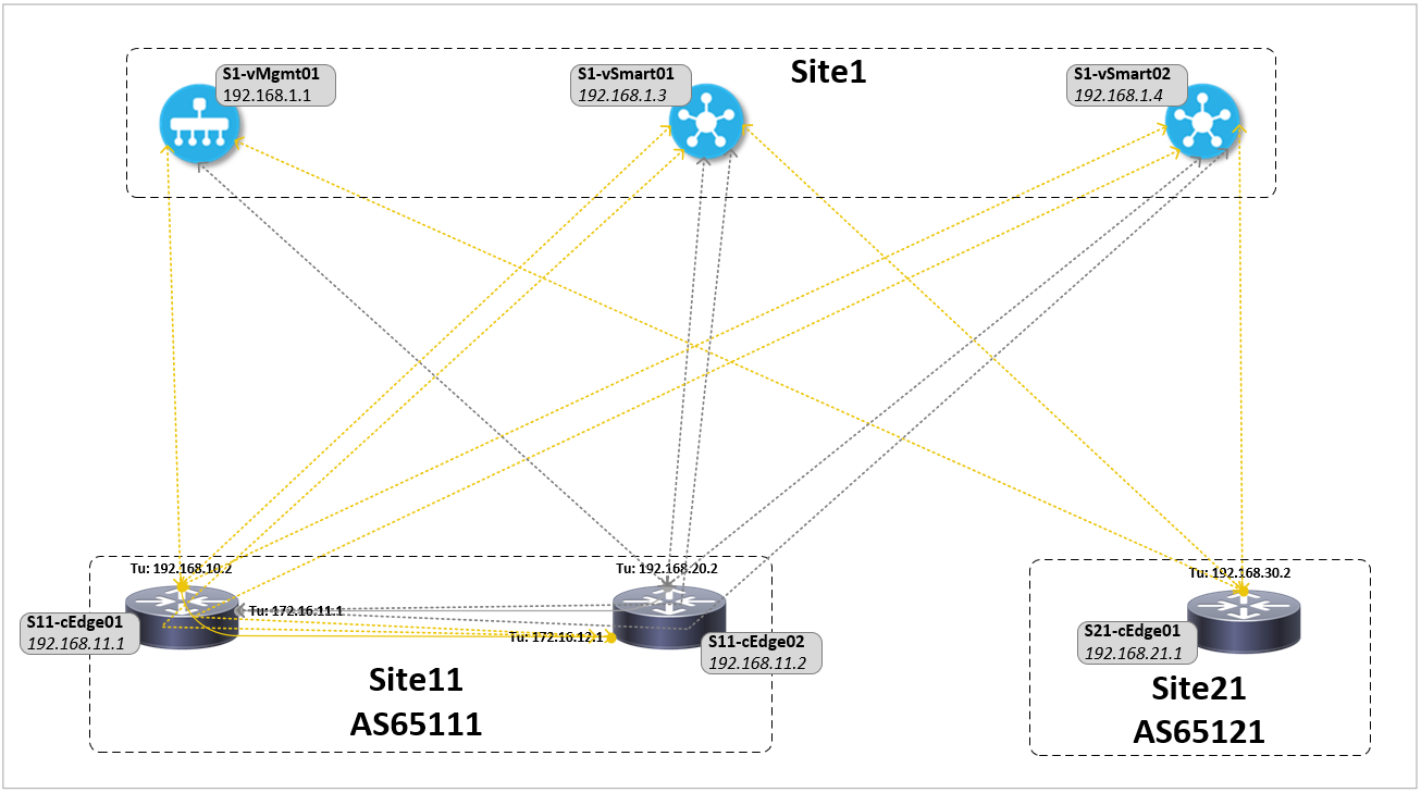
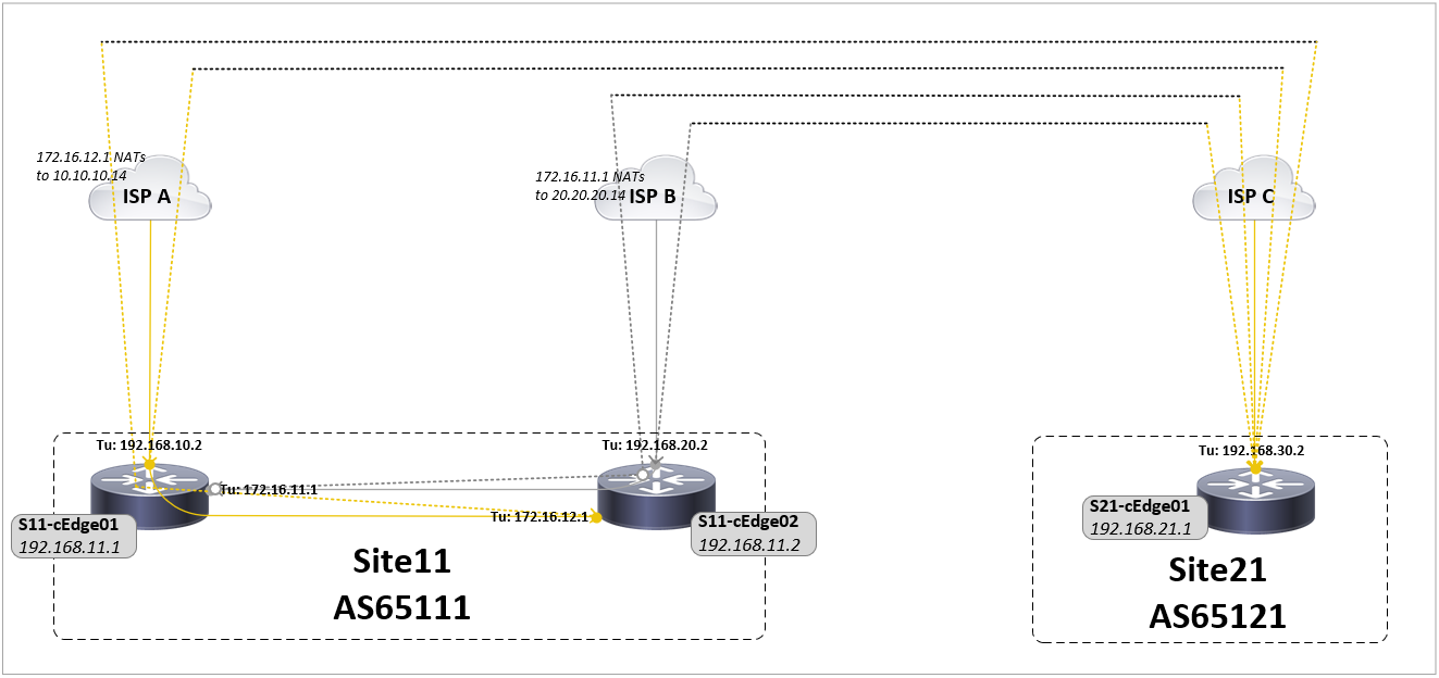
The configuration for this network can be found here, in summary:
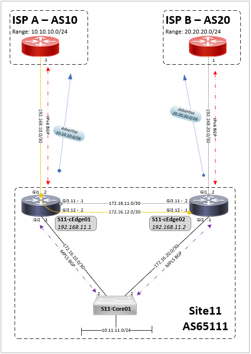
- The SD-WAN vManage, vBond and vSmart are at a site external to the cEdge routers (CSR 1000v)
- Each site has transport-side eBGP peers to ISPs and service-side iBGP MPLS-VPN peerings to core switches
- A default route is advertised by the ISPs (removed later) and a /28 address range advertised out to the ISPs
- Both sites have a Gold TLOC to one ISP with site 11 also having a Silver TLOC
- Site 21 has a TLOC extension between routers to allow the ISP connections (TLOCs) to be shared
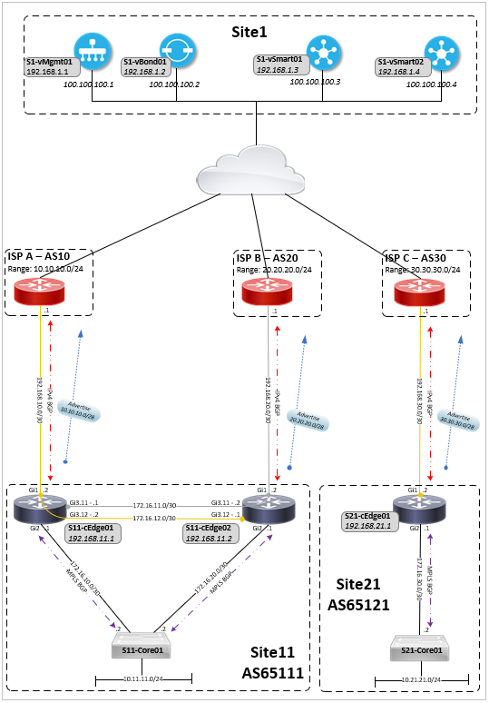
Table Of Contents
Transport-side (VPN0) ISP BGP peering
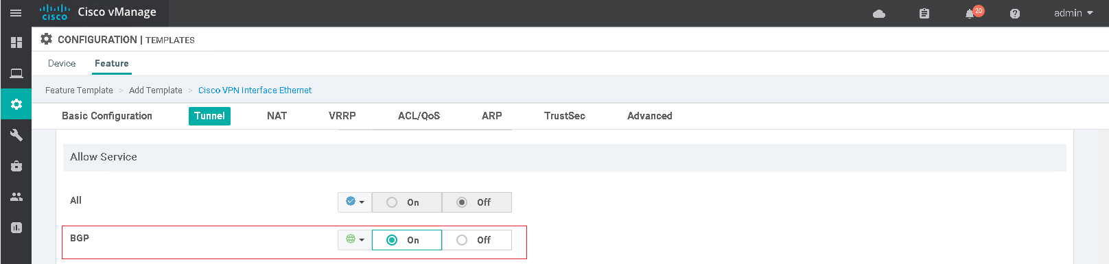
When a physical interface is made a tunnel-interface it becomes a hardened SD-WAN interface that will only allow certain traffic in/out such as tunnel traffic (GRE or IPsec) or native traffic (DNS, NETCONF, SSHD, etc) destined to the router itself. It is possible to allow additional services such as OSPF or BGP over the tunnel interface which is required for routing peerings to be able to form out of the physical interfaces associated to that tunnel. The configuration of the allowed services is done under the VPN0 feature template.
interface Tunnel1
 ip unnumbered GigabitEthernet1
 tunnel source GigabitEthernet1
 tunnel mode sdwan
!
interface GigabitEthernet1
 description UPLINK - ISP A
 ip address 192.168.10.2 255.255.255.252
!
sdwan
 interface GigabitEthernet1
  tunnel-interface
   encapsulation ipsec weight 1
   color gold
   allow-service bgp
   << rest of config omitted for brevity >>
The BGP configuration for this is pretty much the same as you would expect on a standard CSR setup. One nuance with SD-WAN in comparison to IOS-XE is that the BGP configuration can not reference a route-map if it does not already exist otherwise the template push will fail. The route-map must first be created as route-policy within a localised policy and attached as an Additonal Template within the device template (alternatively use CLI a feature template) before it can be referenced by BGP.
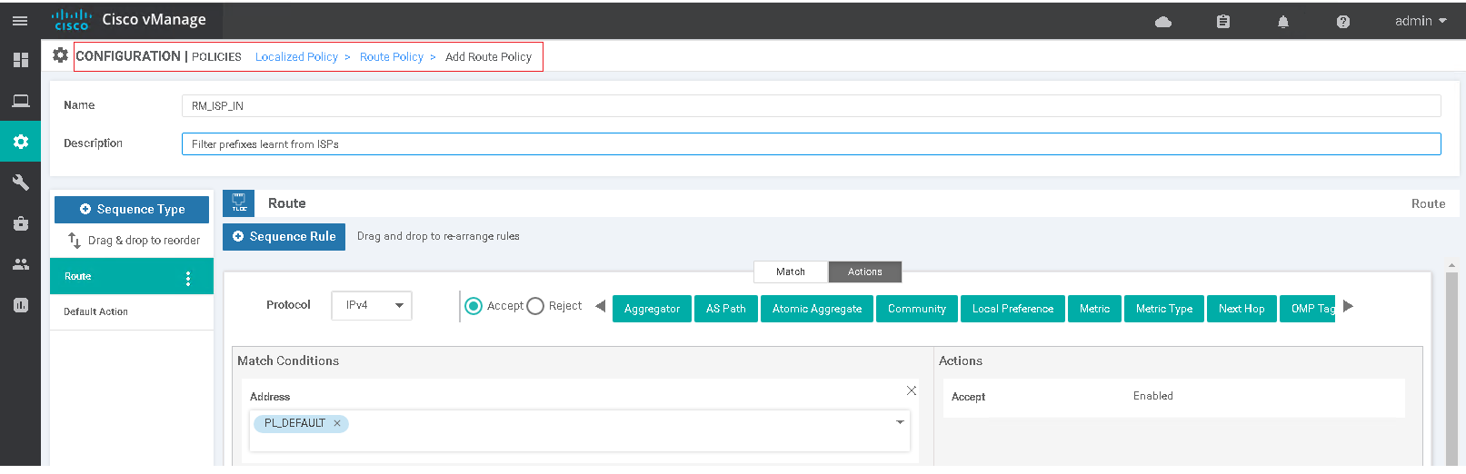
policy
 route-policy RM_ISP_IN
    sequence 1
     match
      address PL_DEFAULT
     action accept
  default-action reject
 !
 lists
  prefix-list PL_DEFAULT
   ip-prefix 0.0.0.0/0
The resulting configuration pushed to the cEdge device is the same as it would be with IOS-XE.
ip prefix-list PL_DEFAULT seq 5 permit 0.0.0.0/0
!
route-map RM_ISP_IN permit 1
 match ip address prefix-list PL_DEFAULT
route-map RM_ISP_IN deny 65535
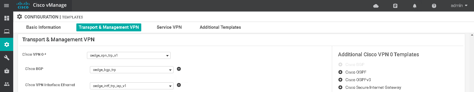
A BGP feature template defines the global BGP configuration with the IPv4 address family neighbor holding the peering information. A null route is required under the VPN0 template to allow for BGP to advertise the public range to the ISP.
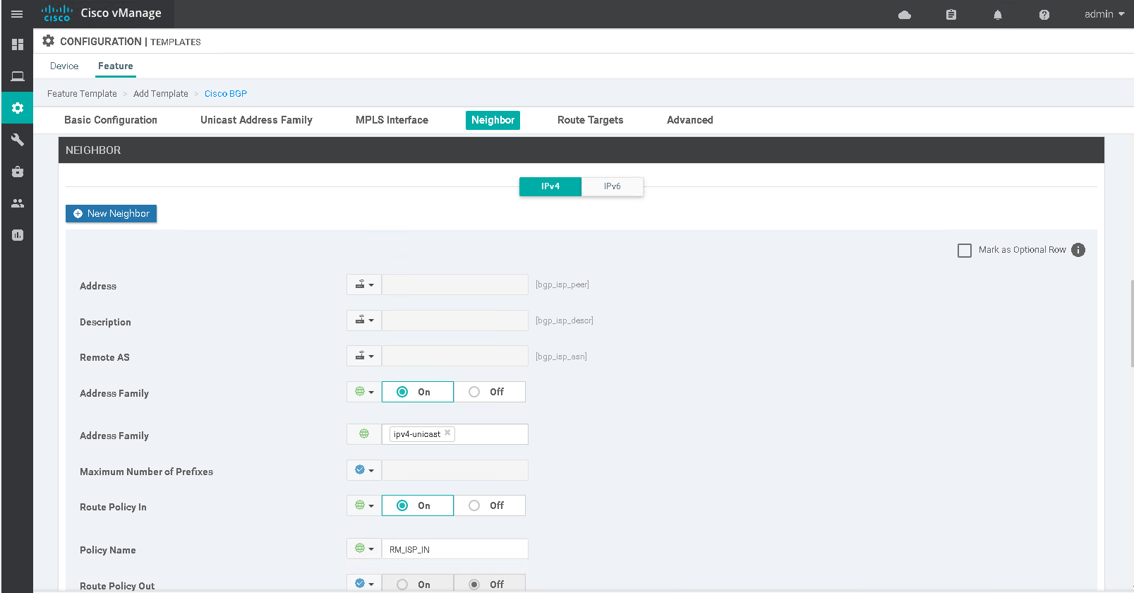
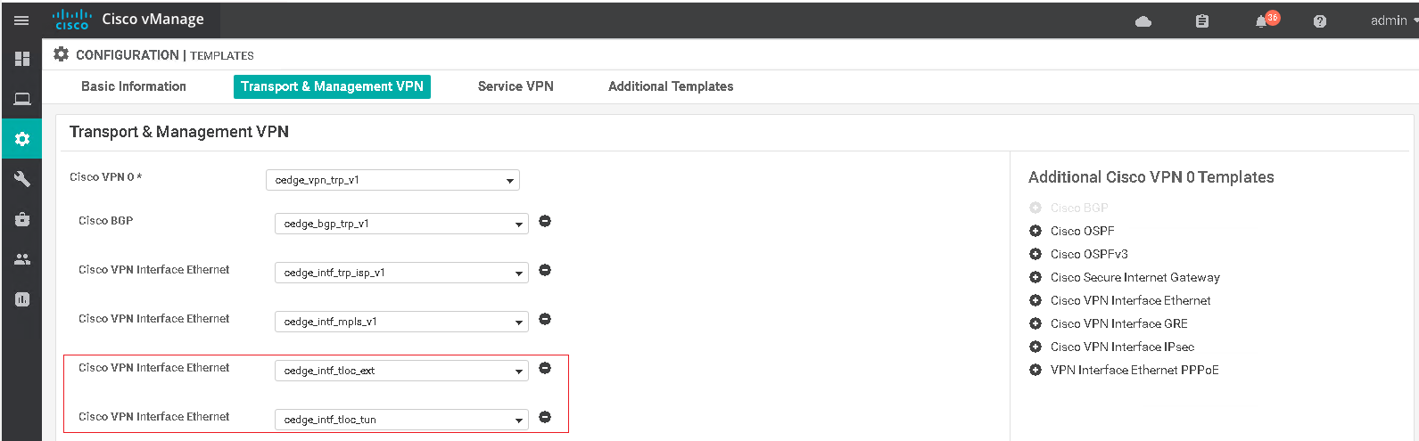
The BGP template is attached to the VPN0 transport section of the device template along with the VPN0 and interface feature templates.
ip route 0.0.0.0 0.0.0.0 192.168.10.1
!
router bgp 65111
 bgp log-neighbor-changes
 timers bgp 9 27
 neighbor 192.168.10.1 remote-as 10
 neighbor 192.168.10.1 description ISP A
 address-family ipv4
  network 10.10.10.0 mask 255.255.255.240
  neighbor 192.168.10.1 activate
  neighbor 192.168.10.1 send-community both
  neighbor 192.168.10.1 route-map RM_ISP_IN in
  distance bgp 20 200 20
 exit-address-family
The global routing table (transport VPN0) can have multiple different default routes with static routes (AD 1) being more preferred over eBGP (AD 20) and ECMP used for routes with the same AD and metric. Default routes are only used to form the control connections (DTLS tunnels to vSmart, vBond and vManage) and DIA, the actual TLOC used for data plane traffic (and possibly DIA) is dependant on OMP and centralised policy.
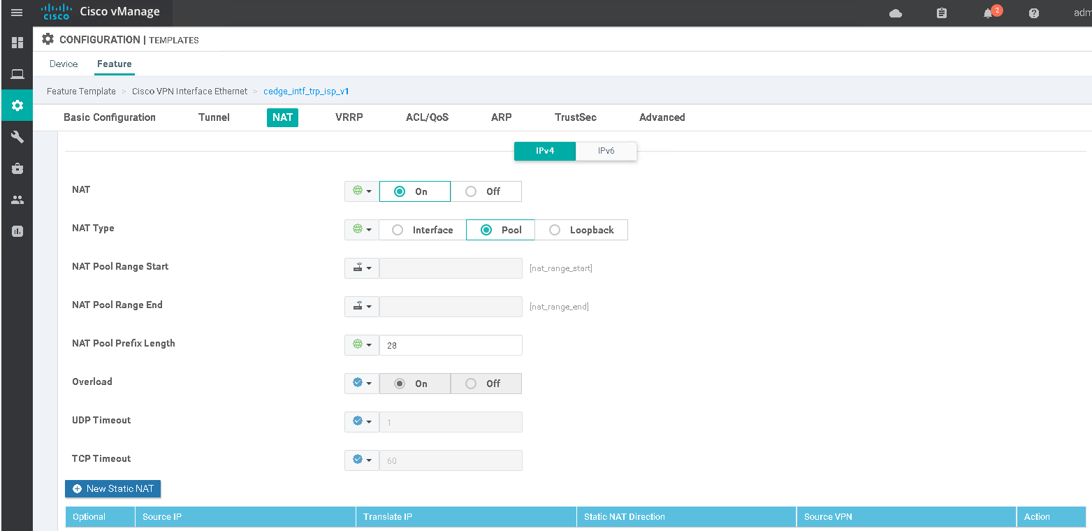
NAT DIA
Enabling any of the 3 NAT types within the interface feature template will add nat outside to the interface. Additional static NAT statements can be used in collaboration with any of these types.
interface GigabitEthernet1
 ip nat outside
The configuration generated by SD-WAN transport-side NAT will look familiar to anyone who has used NAT on IOS or IOS-XE, the one difference being the lack a NAT inside interface. The nat-dia-vpn-hop-access-list or global-list ACLs are not visible in the running config or in the output of show ip access-lists, to edit this in SD-WAN a data policy is used (not sure what default is, maybe any).
NAT Interface: NATs all Internet bound traffic to the physical interface address
ip nat inside source list nat-dia-vpn-hop-access-list interface GigabitEthernet1 overload
NAT pool: NATs all Internet bound traffic to IPs from a pool of addresses
ip nat pool natpool-GigabitEthernet1-0 20.20.20.14 20.20.20.15 prefix-length 28
ip nat inside source list global-list pool natpool-GigabitEthernet1-0 overload egress-interface GigabitEthernet1
NAT Loopback: NATs all Internet bound traffic to the loopback interface address (loopback does not need NAT configured)
ip nat inside source list global-list interface Loopback99 overload egress-interface GigabitEthernet1
Static NAT: One-to-One NAT, can optionally specify the VRF which the NAT traverses
ip nat inside source static 10.11.11.51 20.20.20.12 egress-interface GigabitEthernet1
ip nat inside source static 10.11.11.52 20.20.20.13 vrf 3001 egress-interface GigabitEthernet1
To make use of the DIA NATs in a service-side VPN (VRF) a static route is required with the gateway being the VPN to route traffic from the service-side VRF to the transport-side (VPN 0).
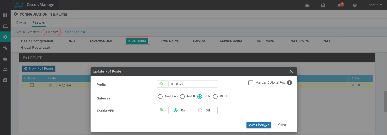
ip nat route vrf 3001 0.0.0.0 0.0.0.0 global
This results in a NAT DIA default route being added to the VPNs routing table. By default a static route has an AD of 1, NAT DIA 6 and OMP 251, meaning that the NAT DIA route overwrites any OMP advertised default route to prefer the local Internet breakout over a remotely learned route.
# show ip route vrf 3001
       n - NAT, Ni - NAT inside, No - NAT outside, Nd - NAT DIA
       ia - IS-IS inter area, * - candidate default, U - per-user static route

n*Nd  0.0.0.0/0 [6/0], 00:02:53, Null0
The NAT DIA route is removed if the NAT transport interfaces are down or the transport static route removed. NAT maintains a translation table that tracks outbound sessions from the service-side VPNs to allow the return traffic to be sent back without having to leak service VPN routes into VPN 0. This default route can be advertised to the networks south of the cEdge router by redistributing it into BGP using redistribute nat-route dia and default-information originate.
An alternative option to routing is to use the centraslied data policy to match on a range of addresses with an action of nat use-vpn 0 to direct the matched data traffic to an Internet exit point on the local router. Is similar to PBR in the sense it will blindly pass traffic out of this interface so needs to be used in conjunction with DIA tracking and NAT fallback.
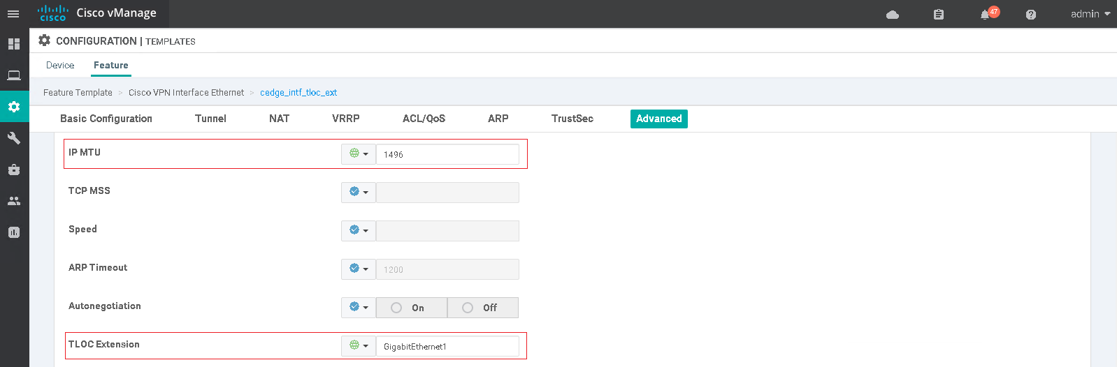
TLOC extension
The above BGP configuration worked fine until I wanted to introduce a TLOC extension into the equation. The use case for the TLOC extension is to have different ISPs on 2 different routers and allow either router to use the opposing routers connection as if it was a directly attached tunnel interface with its own TLOC color.
The TLOC extension logic is pretty straightforward, a link between routers with one end being a tunnel interface and the other end linking that interface to the actual ISP transport interface on the neigbor router (tloc-extension x). To allow for the reverse traffic and future TLOC extensions is better to use sub-interfaces, the sub-interface MTU must be 4 bytes less than the parent interface or the template push will fail.
As with the ISP tunnel interface a default route is required in the outbound direction so that the DTLS tunnels can be formed over this new tunnel interface with all controllers. The next-hop will be the IP address of the TLOC extended end of the link (has tloc-extension cmd).
Applying the static default routes broke the existing DTLS tunnels as the static route had a lower AD (1) than eBGP routes (20) meaning that the BGP route was removed from the routing table. ECMP only works for routes that are sourced by the same routing protocol (static route, BGP, etc) so changing the AD wont work. I could have probably fixed this by running BGP over the TLOC extensions but this adds too much complexity (need per-TLOC extension BGP peers and route filtering) so instead swapped the BGP learnt ISP default routes for static default routes.
S11-cEdge01
interface GigabitEthernet3
 no ip address
 negotiation auto
interface GigabitEthernet3.11
 description TLOC EXT - Tunnel end
 encapsulation dot1Q 11
 ip address 172.16.11.1 255.255.255.252
 no ip redirects
 ip mtu 1496
interface GigabitEthernet3.12
 description TLOC EXT - Extension end
 encapsulation dot1Q 12
 ip address 172.16.12.2 255.255.255.252
 no ip redirects
 ip mtu 1496
!
interface Tunnel11003
 ip unnumbered GigabitEthernet3.11
 no ip redirects
 tunnel source GigabitEthernet3.11
 tunnel mode sdwan
!
ip route 0.0.0.0 0.0.0.0 172.16.11.2
ip route 0.0.0.0 0.0.0.0 192.168.10.1
!
sdwan
interface GigabitEthernet3.12
  tloc-extension GigabitEthernet1
interface GigabitEthernet3.11
  tunnel-interface
   encapsulation ipsec weight 1
   color silver
   no allow-service all
   no allow-service bgp
   << rest of config omitted for brevity >>
S12-cEdge01
interface GigabitEthernet3
 no ip address
 negotiation auto
interface GigabitEthernet3.11
 description TLOC EXT - Extension end
 encapsulation dot1Q 11
 ip address 172.16.11.2 255.255.255.252
 no ip redirects
 ip mtu 1496
interface GigabitEthernet3.12
 description TLOC EXT - Tunnel end
 encapsulation dot1Q 12
 ip address 172.16.12.1 255.255.255.252
 no ip redirects
 ip mtu 1496
!
interface Tunnel12003
 ip unnumbered GigabitEthernet3.12
 no ip redirects
 tunnel source GigabitEthernet3.12
 tunnel mode sdwan
!
ip route 0.0.0.0 0.0.0.0 172.16.12.2
ip route 0.0.0.0 0.0.0.0 192.168.20.1
!
sdwan
interface GigabitEthernet3.11
  tloc-extension GigabitEthernet1
interface GigabitEthernet3.12
  tunnel-interface
   encapsulation ipsec weight 1
   no border
   color gold
   no allow-service all
   no allow-service bgp
   << rest of config omitted for brevity >>
Tracking
The use of a static rather than a BGP learnt default route introduces the possibility of blackholing in the event of an ISP failure. This is not a problem for traffic that would normally be sent over the tunnels (inter SD-WAN site traffic) as the BFD sessions over the tunnels would fail, however some sort of tracking is needed for DIA traffic. SD-WAN has 2 native Viptela tracker features that use HTTP port 80 probes expecting a 200 OK response.
- DIA tracker: Tracks the status of the transport interface it is associated by periodically probing a specified addresses (interface IP used as source of probes) to measure the round-trip-time. When the latency exceeds the configured threshold the tracker considers the network as unavailable causing the router to withdraw the NAT route from service-side VPNs and re-route traffic based on the local routing table.
- Static-route tracker (service-side VPN only): Determines if a service-side static route can be included in the routing table of a device based on the availability of the tracked endpoint address. If the tracker does not receive a response to its probes the static route is not included in the routing table and is not advertised to OMP. It is also possible configure an alternative next-hop address or a static route with a higher administrative distance to provide a backup path.
Newer versions of code support additional DIA tracker features:
- From 17.7.1a you can configure a tracker group with two trackers (AND or OR logic) and associate this tracker group to an interface
- Supported Interfaces for NAT DIA Tracker are Cellular, Ethernet, PPPoE, sub-interfaces (17.7.1a) and DSL dialer (17.6.x). Only one tracker or tracker group can be applied to an interface
- DNS URL endpoint is not supported on Cisco IOS XE SD-WAN devices
- NAT fallback feature for IOS-XE is supported only from 17.3.2
Trackers are configured under the system feature template and then associated under the relevant transport interface feature template. The interface must have NAT enabled or else the deployment will fail.
| Parameter | Range | Default | Description |
|---|---|---|---|
| Threshold | 100 - 1000 | 300 | Duration in ms to wait for the probe to return a response before declaring transport interface as down |
| Interval | 20 - 600 | 60 | Frequency in seconds at which a probe is sent to determine the status of the transport interface |
| Multiplier | 1 - 10 | 3 | Number of times a probe can be resent before declaring that the transport interface is down |
![]()
![]()
endpoint-tracker umbrella
 endpoint-ip 208.67.222.222
 tracker-type interface
 threshold 200
 multiplier 3
 interval 20
!
interface GigabitEthernet1
 endpoint-tracker umbrella
A few useful commands for viewing the tracker
show endpoint-tracker recordsShow all trackers and the settings show endpoint-trackerShow associated trackers and statistics show endpoint-tracker tracker-groupShow tracker groups show endpoint-tracker static-routeShow static-route trackers and statistics show ip sla summaryShows used trackers and the statistics
Control and Data plane
Cisco SD-WAN uses DTLS or TLS tunnels for the control plane and IPsec or GRE tunnels for the data plane.
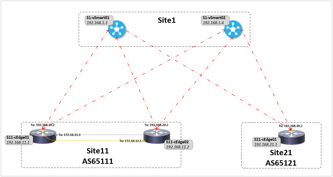
Control plane
A DTLS tunnels is formed to every vSmart controller over each transport tunnel interface (TLOC color) of the WAN Edge device. As the TLOC extensions are also tunnel interfaces control connections are also formed over them to each vSmart controller. Only one DTLS tunnel is formed to the vManage over the local transport interface, not over the TLOC extension.
show sdwan control local-properties
show sdwan control connections
show sdwan control connection-history
S11-cEdge01#show sdwan control connections
                                                                                       PEER                                          PEER                                          CONTROLLER
PEER    PEER PEER            SITE       DOMAIN PEER                                    PRIV  PEER                                    PUB                                           GROUP
TYPE    PROT SYSTEM IP       ID         ID     PRIVATE IP                              PORT  PUBLIC IP                               PORT  LOCAL COLOR     PROXY STATE UPTIME      ID
----------------------------------------------------------------------------------------------------------------------------------------------------------------------------------------
vsmart  dtls 192.168.1.3     1          1      100.100.100.3                           12346 100.100.100.3                           12346 silver          No    up     1:19:32:26  0
vsmart  dtls 192.168.1.4     1          1      100.100.100.4                           12346 100.100.100.4                           12346 silver          No    up     1:19:32:26  0
vsmart  dtls 192.168.1.3     1          1      100.100.100.3                           12346 100.100.100.3                           12346 gold            No    up     1:19:55:09  0
vsmart  dtls 192.168.1.4     1          1      100.100.100.4                           12346 100.100.100.4                           12346 gold            No    up     1:19:55:09  0
vmanage dtls 192.168.1.1     1          0      100.100.100.1                           12346 100.100.100.1                           12346 gold            No    up     1:19:55:09  0
OMP peerings
OMP peers are established between from the system IPs of the routers to each vSmart controller over the DTLS tunnels. OMP peerings are per-device, unlike DTLS tunnels they are NOT per-transport. vSmarts act as route reflectors advertising all prefixes they learn from WAN Edge routers back out to all other WAN Edge routers (RR clients).
show sdwan omp peers
show sdwan omp routes
show sdwan omp routes [vpn <vrf>  <x.x.x.x/x> [detail]]
show sdwan omp routes [vpn <vrf>  <x.x.x.x/x> [advertised | received]]
show sdwan omp tlocs [table]                          Table doesnt work on some platforms so need to use include
show sdwan omp tlocs | in tloc|peer      |site-id|bfd|gold|silver
show sdwan omp services [<service>]
show sdwan ip fib vpn <vpn>
S11-cEdge02#show sdwan omp peers
R -> routes received               I -> routes installed              S -> routes sent

                         DOMAIN    OVERLAY   SITE
PEER             TYPE    ID        ID        ID        STATE    UPTIME           R/I/S
------------------------------------------------------------------------------------------
192.168.1.3      vsmart  1         1         1         up       1:20:16:18       3/1/2
192.168.1.4      vsmart  1         1         1         up       1:20:16:18       3/0/2
OMP advertises three types of routes to all routers:
- OMP routes: Local service-side routes used for reachability between endpoints at different sites
- TLOCs routes: Identifiers that tie an OMP route to a physical location. Is the only entity of the OMP domain that is visible to the underlying network so it must be reachable via the underlay
- Service routes: Identifiers that tie an OMP route to a service in the network (firewall, IPS, load balancer, etc), specifying the location of the service in the network. Service route information is carried in both service and OMP routes
It is by choosing what TLOCs are advertised that the SD-WAN centralised control policy forms the network topology, for example hub-and-spoke or full mesh. A router will only put a route in its routing table if it has a route to the next-hop TLOC of that route (similar to how BGP will not add a route if the next-hop is inaccessible).
Data plane
IPsec tunnels are created between the TLOCs (keys are exchanged in OMP updates) of differing WAN Edge devices with BFD sessions (also used for AAR Quality of Experience measurements) then formed over these tunnels to establish the data plane. It is over these tunnels that traffic is routed using OMP route information learnt via OMP over the control connections.
IPsec tunnels and BFD sessions are never formed between any WAN edge devices in the same site. In this setup TLOC extensions are used to allow the same type of redundancy that you would have with iBGP peers between edge routers in the same site in a traditional network setup.
show sdwan ipsec inbound-connections
show sdwan ipsec outbound-connections
show sdwan bfd sessions
show sdwan bfd history
show sdwan tunnel statistics table
show ip route vrf <vpn>
show sdwan ip fib vpn <vpn>
S21-cEdge01#show sdwan bfd sessions
                                    SOURCE TLOC      REMOTE TLOC                                      DST PUBLIC                      DST PUBLIC         DETECT      TX
SYSTEM IP        SITE ID  STATE       COLOR            COLOR            SOURCE IP                       IP                              PORT        ENCAP  MULTIPLIER  INTERVAL(msec) UPTIME          TRANSITIONS
-------------------------------------------------------------------------------------------------------------------------------------------------------------------------------------------------------------
192.168.11.1     11       up          gold             silver           192.168.30.2                    20.20.20.14                     12406       ipsec  7           1000           1:18:46:58      0
192.168.11.1     11       up          gold             gold             192.168.30.2                    192.168.10.2                    12386       ipsec  7           1000           1:19:00:09      2
192.168.11.2     11       up          gold             gold             192.168.30.2                    10.10.10.14                     12406       ipsec  7           1000           1:18:46:52      0
192.168.11.2     11       up          gold             silver           192.168.30.2                    192.168.20.2                    12386       ipsec  7           1000           1:19:00:17      2
In this example topology the vSmart controllers (route-reflectors) advertise (reflect) prefixes learnt from S11-cEdge01 back to S11-cEdge02. S11-cEdge02 does NOT put these routes in local routing table as they are marked as INV, U (invalid, TLOC unresolved) as the next-hop (TLOC, so tunnel of S11-cEdge01) is unreachable as the BFD tunnel (data plane) to it is down.
S11-cEdge02#show sdwan omp routes
Code:
C   -> chosen        I   -> installed            Red -> redistributed        Rej -> rejected      L   -> looped        IA  -> On-demand inactive
R   -> resolved      S   -> stale                Ext -> extranet             Inv -> invalid       Stg -> staged        U   -> TLOC unresolved
                                            PATH                      ATTRIBUTE
VPN    PREFIX              FROM PEER        ID     LABEL    STATUS    TYPE       TLOC IP          COLOR            ENCAP  PREFERENCE
--------------------------------------------------------------------------------------------------------------------------------------
3001   10.11.11.0/24       0.0.0.0          75     1002     C,Red,R   installed  192.168.11.2     gold             ipsec  -
                           0.0.0.0          76     1002     C,Red,R   installed  192.168.11.2     silver           ipsec  -
                           192.168.1.3      14     1002     Inv,U     installed  192.168.11.1     gold             ipsec  -
                           192.168.1.3      15     1002     Inv,U     installed  192.168.11.1     silver           ipsec  -
                           192.168.1.4      13     1002     Inv,U     installed  192.168.11.1     gold             ipsec  -
                           192.168.1.4      14     1002     Inv,U     installed  192.168.11.1     silver           ipsec  -
3001   10.21.21.0/24       192.168.1.3      13     1002     C,I,R     installed  192.168.21.1     gold             ipsec  -
                           192.168.1.4      12     1002     C,R       installed  192.168.21.1     gold             ipsec  -

S11-cEdge02#show sdwan omp tlocs | in tloc|peer      |site-id|bfd|gold|silver
tloc entries for 192.168.11.1
                 gold
peer            192.168.1.3
     bfd-status        down
     site-id           11
peer            192.168.1.4
     bfd-status        down
     site-id           11
tloc entries for 192.168.11.1
                 silver
peer            192.168.1.3
     bfd-status        down
     site-id           11
peer            192.168.1.4
     bfd-status        down
     site-id           11
tloc entries for 192.168.11.2
                 gold
peer            0.0.0.0
     bfd-status        up
     site-id           11
tloc entries for 192.168.11.2
                 silver
peer            0.0.0.0
     bfd-status        up
     site-id           11
tloc entries for 192.168.21.1
                 gold
peer            192.168.1.3
     bfd-status        up
     site-id           21
peer            192.168.1.4
     bfd-status        up
     site-id           21
Reference links
For anything SD-WAN based you cant go wrong with the free content on Network Academy, it is better than you will find on many of the paid courses out there. Below are a few of the Cisco guides on the subjects mentioned.
https://www.cisco.com/c/en/us/td/docs/routers/sdwan/configuration/routing/vEdge-20-x/routing-book/m-unicast-routing.html https://www.cisco.com/c/en/us/td/docs/routers/sdwan/configuration/system-interface/ios-xe-17/systems-interfaces-book-xe-sdwan/track-static-route-ios-xe.pdf https://www.cisco.com/c/en/us/td/docs/routers/sdwan/configuration/nat/nat-book-xe-sdwan/configure-nat.html