Over the years I have built numerous IPsec VPNs on ASAs using crypto maps and an ACL for the interesting traffic. For a simple solution to join small sites with no need for routing these work great and keep the complexity down to a minimum. For more complex environments or cloud connectivity you are probably going to need to use VTIs, this post goes through the process of building VTI VPNs between an ASR and ASA.
Site-to-site VPNs using crypto maps with an interesting traffic ACL seem to have got a lot of bad press over the years. They can be problematic between different vendors using a mix of policy-based (ACL interesting traffic) and route-based (tunnel interface) VPNs, but if you stick to the basics they are pretty solid. If you need simple tunnel between sites for a few networks they are perfect as you can get away from any unnecessary complexity such as running routing protocols. Alternatively, if you did want to complicate it a little you can run BGP through the tunnel or GRE and run a routing protocol over the GRE tunnel.
I have used this later option for connections between various sites for the last few years with no real issues. An IPSec VPN between ASA and ASR with a GRE tunnel inside that (GRE tunnel source and destination as the interesting traffic) and OPSF running over the GRE tunnel. See my earlier post vCentre in Azure for more detail on a similar setup.
We recently changed this design to use VXLAN/BGP rather than GRE/OSPF which brought to light a crypto map limitation that meant we had to change the VPNs to use VTIs. I thought it was worth a quick post on the VPN elements and how these are configured.
VRF-Aware IPsec
With VRF-Aware IPsec VPN tunnels the outer encapsulated packet belongs to one VRF domain (fVRF) whilst the inner protected IP packet belongs to another (iVRF).
- iVRF (inside VRF): The VRF that contains the clear-text traffic before encryption (outbound flows) or after decryption (inbound flows)
- fVRF (front-door VRF or outside VRF): The VRF that contains the encrypted traffic
When VRF-Aware IPsec is used with a crypto map this crypto map cannot use the global VRF as the iVRF and a non-global VRF as the fVRF. In our VXLAN design the global routing table is the underlay advertising loopbacks which are then used to build the overlay of VTEP tunnels and BGP peerings. Therefore, the VPN interesting traffic needed to be the loopbacks (in the global routing table) so that the VTEP tunnels could be built between sites. For this reason we had to move away from crypto maps and use VTIs as the do not have that limitation.
Encryption and Authentication with IKEv2
AES-GCM is a more secure cipher than AES-CBC and as it is written in parallel the throughput is significantly higher due to lower encryption overheads compared to serial encryption. Each block can be encrypted independently with the operation carried out in parallel both for encryption and decryption. As it provides both data authenticity (integrity) and confidentiality there is need to configure the integrity separately.
DH type:
- If you are using encryption or authentication algorithms with a 128-bit key, use Diffie-Hellman groups 19, 20.
- If you are using encryption or authentication algorithms with a 256-bit key or higher, use Diffie-Hellman group 21.
Anti-replay
IPSec provides anti-replay protection against duplicate encrypted packets with the assignment of a monotonically increasing sequence number to each encrypted packet. The receiving IPSec endpoint keeps track of which packets it has already processed on the basis of these numbers with the use of a sliding window (anti-replay window) of all acceptable sequence numbers.
If the window size is too small the packet will get dropped due to a replay failure, it is not really an attack. The default size of 64 is considered impractically small for modern networks (azure VPN uses 1024), there are currently feature requests to change the default anti-replay window size in Cisco IOS to 512. If you leave it this set at a low value you will likely get anti-replay errors like these in the logs:
Jan  6 2021 09:57:03.695 GMT: %IOSXE-3-PLATFORM: R0/0: cpp_cp: QFP:0.0 Thread:021 TS:00005309662244527188 %IPSEC-3-REPLAY_ERROR:
IPSec SA receives anti-replay error, DP Handle 7, src_addr 4.4.4.4, dest_addr 3.3.3.3, SPI 0x7a857081
In such scenarios you can increase the size of the replay window in order to ensure that such delays are accounted for and prevent legitimate packets from being dropped. If you increase the size it does not greatly increase the risk of an attack, but like most things it is a weigh up between security and performance as this is a global setting on certain systems (for all VPNs) and should be done at both ends.
MTU and MSS
Whenever dealing with VPNs you need to take into account the extra headers that will be added and adjust the MTU and MSS accordingly. If you don’t you may get away with it to start with, but trust me it will come back to bite you at some point.
- MTU: The largest packet or frame size that can be sent on the wire. The default is 1500 with 40 of that being for the IP and TCP header leaving 1460 bytes of data.
- TCP MSS: The largest amount of data that a device can receive in a single TCP segment (excluding IP and TCP header). The MSS announcement (often mistakenly called a negotiation) is sent during the three-way handshake by both sides, it says ‘I can accept TCP segments up to size’. This is not negotiated, each end can use a different value making upload and download speeds inconsistent.
- Fragmentation: Divides the datagram into pieces with each piece small enough to pass over the single link that it is being fragmented for (MTU of the interface). This fragmentation process takes place at the IP layer (OSI layer 3) marking the packets it fragments.
- tcp adjust-mss: Adjusts the MSS value of the TCP SYN packets for packets going through a router. This is done for both directions of the traffic flow, so it adjusts the MSS of both the sender and receiver in a conversation. It is effective only for TCP connections.
- PMTUD: Method used by endpoints to dynamically discover the lowest possible MTU along a path by setting the ‘Don’t Fragment’ (DF) bit in the IP header of each packet. Is fine in a controlled environment, however as many devices block ICMP can be unreliable across the Internet.
Fragmentation should be avoided if possible as it is not supported by all applications and due to the inconsistences in performance can be a real nightmare to identify and troubleshoot. If the fragmentation was done on the VPN router it may affect throughput as the router has to offload the encryption to the hardware. It is recommended to offload the fragmentation on to the end host by lowering the tunnel MTU (applies to UDP and TCP) and/or setting adjust-mss (TCP only) to make the endpoints to send smaller packets.
The DF bit is not copied into the GRE-encapsulated packet meaning PMTUD doesn’t work with GRE so the MTU and MSS must be statically set on the GRE tunnel interface. Due to the additional packet overhead added by introducing layers of encryption (IPsec up to 74bytes, GRE either 4 or 24 Bytes) the normal standard is to set the MTU to 1400 and MSS to 1360 (MTU minus 20 byte IP header and 20 byte TCP header).
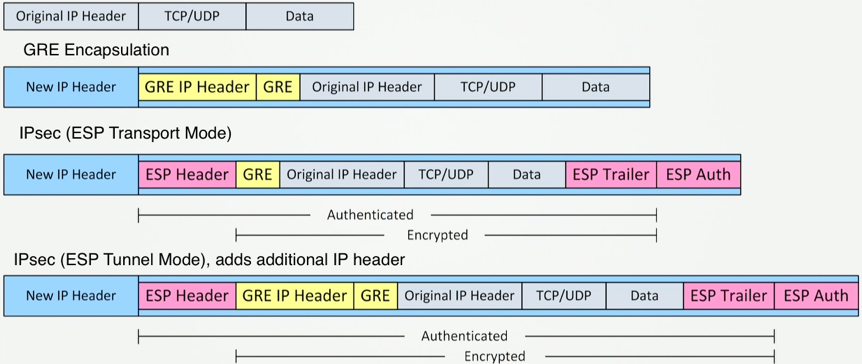
The size of the IPsec headers will vary dependant on the algorithms used. A VTI interface or IPsec tunnel will automatically workout the size of the extra header and adjust the MTU accordingly. For example here the MTU is 1438, so the IPsec headers are 62 bytes.
ASR-WAN01#show crypto ipsec sa | in mtuplaintext mtu 1438, path mtu 1500, ip mtu 1500, ip mtu idb GigabitEthernet0/0/4
ASR-WAN01#show int tun11 | in MTUTunnel transport MTU 1438 bytes
ASA-XFW01/act/pri# show crypto ipsec sa peer 3.3.3.3 | in overheadpath mtu 1500, ipsec overhead 63(44), media mtu 1500
As we are using VXLAN instead of GRE the added header is now 50 rather than 24 bytes:
MTU: 1500 - (50 (VXLAN) + 62 (IPSEC)) = 1388
MSS: 1500 - (50 (VXLAN) + 62 (IPSEC) + 20 (IP) + 20 (TCP)) = 1348
BGP through an ASA
By default an ASA will strip TCP option 19 and perform TCP Sequence Number Randomization on every session passing through it. TCP option 19 is a TCP extension used to carry the MD5 digest in a TCP segment, BGP authentication through and ASA will fail without it. To allow this the following is needed:
access-list GLOBAL_POLICY_BGP_TCP179 extended permit tcp any any eq bgp
class-map CM_BGP
 match access-list GLOBAL_POLICY_BGP_TCP179

tcp-map TCP_MD5_ALLOW

policy-map global_policy
class CM_BGP
  set connection random-sequence-number disable
  set connection advanced-options TCP_MD5_ALLOW
Building the VPN
ASA Configuration
1. Phase1 policy: IKEv2 must be enabled on the interface through which the VPN is formed. Integrity is null as GCM has built in integrity
crypto ikev2 enable outside

crypto ikev2 policy 5
 encryption aes-gcm-256
 integrity null
 group 21
 prf sha512
 lifetime seconds 86400
2. Phase2 proposal: Once again integrity is null
crypto ipsec ikev2 ipsec-proposal PH2_PROP_AES_GCM256
 protocol esp encryption aes-gcm-256
 protocol esp integrity null
3. IPsec profile: Holds the IKEv2 proposal and any other IKEv2 settings such as PFS or lifetime (traditionally configured in the crypto map)
crypto ipsec profile PH2_PROF_AES_GCM256
 set ikev2 ipsec-proposal PH2_PROP_AES_GCM256
 set pfs group21
4. Group policy: Enable IKEv2 for this peer as by default it only uses IKEv1
group-policy 3.3.3.3 internal
group-policy 3.3.3.3 attributes
 vpn-tunnel-protocol ikev2
5. Tunnel group: Holds the pre-shared-key with a separate one entered for the local and remote end (can be the same)
tunnel-group 3.3.3.3 type ipsec-l2l
tunnel-group 3.3.3.3 general-attributes
 default-group-policy 3.3.3.3
tunnel-group 3.3.3.3 ipsec-attributes
 ikev2 remote-authentication pre-shared-key my_strong_password
 ikev2 local-authentication pre-shared-key my_strong_password
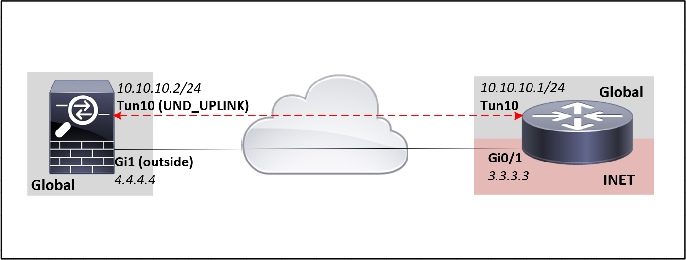
6. Tunnel interface: As per any ASA interface a nameif is required and an ACL can be associated. Specify the interface through which the tunnel will be formed, the remote peer address and associate the IPsec profile (from step 3) which defines the proposal of IKEv2 parameters for phase2
interface Tunnel10
 nameif UND_UPLINK
 ip address 10.10.10.1 255.255.255.252
 tunnel source interface Outside
 tunnel destination 3.3.3.3
 tunnel mode ipsec ipv4
 tunnel protection ipsec profile PH2_PROF_AES_GCM256
 no shut
7. Anti-replay: Global command to increase the the anti-replay window size (applies to all VPN tunnels)
crypto ipsec security-association replay window-size 512
ASR Configuration
1. Phase1 proposal: Holds the Phase1 algorithms, integrity is not required as it is using GCM
crypto ikev2 proposal PH1_PROP_AES_GCM256
 encryption aes-gcm-256
 group 21
 prf sha512
2. Phase1 policy: Binds the phase1 proposal to the relevant fVRF (VRF of the public facing ASR interface) and optionally the interface
crypto ikev2 policy PH1_PLCY_GCM256
 match fvrf INET
 proposal PH1_PROP_AES_GCM256
3. Phase2 Transform-set: Defines the Phase2 algorithms, in tunnel mode the entire original IP packet is protected by IPSec
crypto ipsec transform-set PH2_TRAN_GCM256 esp-gcm 256
  mode tunnel
4. Keyring: Links the PSK and remote peer address (like ASA tunnel-group). A keyring can hold multiple keys, each identified by the peer name
crypto ikev2 keyring PH2_KEYR_DC
 peer ASA-IFW02
  address 4.4.4.4
  pre-shared-key local my_strong_password
  pre-shared-key remote my_strong_password
5. IKEv2 profile: match fvrf is the interface the tunnel is formed over (encrypted traffic) to a remote device with this IP address (match identity remote address). This has to be the true address of the remote device, so if the remote device is NATed will be the private address of that device. Basically says if the peer identity (got from Ph1) matches this address, use these parameters. If the internal VRF (non-encrypted traffic) was not global you would also need to specify that VRF using ivrf xxx. Finally the PSK method is set and the keyring of PSKs associated.
crypto ikev2 profile PH2_IKEV2_PROF_GCM256
 match fvrf INET
 match identity remote address 4.4.4.4 255.255.255.255
 identity local address 3.3.3.3
 authentication local pre-share
 authentication remote pre-share
 keyring local KR_IKEV2_DC
 dpd 10 2 on-demand
6. IPsec profile: Glues together the transform-set, IKEv2-profile (identity, keyring) and other IKEv2 settings such as PFS, lifetime or anti-replay
crypto ipsec profile PH2_IPSEC_PROF_GCM256
 set transform-set PH2_TRAN_GCM256
 set ikev2-profile PH2_IKEV2_PROF_GCM256
 set pfs group21
 set security-association replay window-size 512
7. Tunnel interface: The tunnel itself is within the iVRF (non-encrypted traffic). As it is in the global routing table the VRF does not need setting, if it wasn’t it would be set using vrf forwarding xxx. The tunnel vrf is the fVRF (encrypted traffic) as this is the VRF that the encrypted tunnel traffic will traverse over. The IPsec profile (from step 6) is associated with the interface to define the proposal of IKEv2 parameters for phase2
interface Tunnel10
 description TUN > ASA-XFW01 - Tun10
 bandwidth qos-reference 400000
 ip address 10.10.10.2 255.255.255.252
 tunnel source GigabitEthernet0/1
 tunnel mode ipsec ipv4
 tunnel destination 4.4.4.4
 tunnel vrf INET
 tunnel protection ipsec profile PH2_IPSEC_PROF_GCM256
As mentioned earlier we are running VXLAN over the VPN to link sites with ASAs and ASRs at either end. On an ASR the BDI interfaces are the VXLAN L3VNIs, this is the last point at the site before the traffic is encapsulated inside VXLAN. For this reason this is were you have to set the MSS (ip tcp adjust-mss) for each tenant (VRF, so BDI) to 1348. The same applies for netflow, you configure it on the BDI interface so you can capture the traffic before it is encapsulated inside VXLAN.
References
Some useful links from clever people.
-
Information and various configuration examples for VRF-Aware IPsec
https://integratingit.wordpress.com/2018/06/09/configuring-a-vti-tunnel-between-asa-firewall-and-ios-router/
https://community.cisco.com/t5/security-documents/vrf-aware-ipsec-cheat-sheet/ta-p/3109449
http://aconaway.com/2011/12/12/vrf-aware-ipsec-tunnels/ -
IPSec VPN Solutions Using Next Generation Encryption and the header sizes involved
https://www.cisco.com/c/dam/en_us/solutions/industries/docs/gov/ipsec_vpn_Solutions_using_nge.pdf -
Anti-Replay
https://techstat.net/how-to-fix-ipsec-vpn-anti-replay-errors-on-cisco-ios-and-ios-xe/
https://www.cisco.com/c/en/us/td/docs/ios/sec_secure_connectivity/configuration/guide/convert/sec_ipsec_data_plane_15_1_book/sec_ipsec_antireplay.html
https://networkengineering.stackexchange.com/questions/25655/high-number-of-pkts-replay-failed-on-cisco-asa