The Cisco documentation about this call it Inter-AS Option B with the use case being to extend LSPs between sites over the one link. As Option B is the only MPLS-VPN method supported by Cisco SD-WAN I wanted to get a better understanding of how it works aswell as see if it could be used to extend multi-VRF prefixes between edge routers and a core switch within the same AS (rather than using Option C with LDP).
Table Of Contents
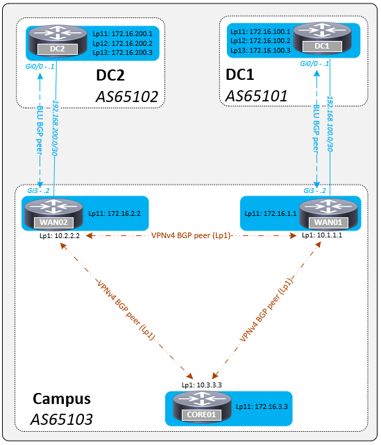
Topology
To quote RFC 3107 (Carrying Label Information in BGP-4):
- If two immediately adjacent Label Switched Routers (LSRs) are also BGP peers, then label distribution can be done without the need for any other label distribution protocol.
- Label mapping information for a particular route is piggybacked in the same BGP Update message that is used to distribute the route itself. When BGP is used to distribute a particular route it also distributes an MPLS label which is mapped to that route.
The lab topology uses the IPv4 address-family underlay to advertise loopbacks (loopback1) that are used to build the the VPNv4 address-family overlay. The reason I did it this way was because I wanted route-through any issues (failures of WAN to Core links) rather than routing-around them (routing convergence).
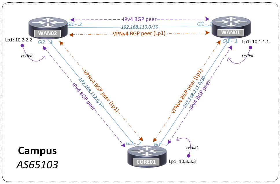
To enabled labelled BGP send-label is added to the underlay (IPv4 address-family) neighbor and mpls bgp forwarding to the physical interface facing that neighbor. The rest of the configuration is pretty standard, I needed to make WAN01 and WAN02 route reflectors on the underlay (route-reflector-client) so that their loopbacks are advertised to the CORE01 in failure scenarios. The configs can be found here.
WAN02# show ip bgp summary | in 19|N
Neighbor        V           AS MsgRcvd MsgSent   TblVer  InQ OutQ Up/Down  State/PfxRcd
192.168.110.1   4        65103      13      13        7    0    0 00:07:02        4
192.168.112.2   4        65103      11      13        7    0    0 00:06:46        3

WAN02# show ip route | in B__
B        10.1.1.1 [200/0] via 192.168.110.1, 00:05:54
B        10.3.3.3 [200/0] via 192.168.112.2, 00:05:54
B        192.168.111.0 [200/0] via 192.168.110.1, 00:05:54

WAN02# show bgp vpnv4 unicast all summary | in 10|N
BGP router identifier 10.2.2.2, local AS number 65103
Neighbor        V           AS MsgRcvd MsgSent   TblVer  InQ OutQ Up/Down  State/PfxRcd
10.1.1.1        4        65103     126     126        6    0    0 00:06:13        0
10.3.3.3        4        65103     127     127        6    0    0 00:06:10        0

WAN02# show mpls interfaces
Interface              IP            Tunnel   BGP Static Operational
GigabitEthernet1       No            No       Yes No     Yes
GigabitEthernet2       No            No       Yes No     Yes
The WAN routers have a BLU VRF BGP peering to external data centres (different ASs) and all devices within the DC and campus advertise loopbacks in to the BLU VRF.
WAN02# show bgp vpnv4 unicast all summary | in 10|N
BGP router identifier 10.2.2.2, local AS number 65103
Neighbor        V           AS MsgRcvd MsgSent   TblVer  InQ OutQ Up/Down  State/PfxRcd
10.1.1.1        4        65103    1802    1802       28    0    0 01:31:51        5
10.3.3.3        4        65103    1801    1803       28    0    0 01:31:48        1
192.168.200.1   4        65102      28      34       28    0    0 00:22:58        4
BGP advertised MPLS Labels
For every prefix a device running labeled BGP (mpls bgp forwarding and send-label) advertises a label is assigned. For example on WAN02 it has a label for its local loopback as well for the loopbacks learnt from the DC2 peering.
WAN02#show mpls forwarding-table
Local      Outgoing   Prefix              Bytes Label   Outgoing        Next Hop
Label      Label      or Tunnel Id        Switched      interface
16         No Label   172.16.200.1/32[V]  11970         Gi3             192.168.200.1
18         No Label   172.16.200.2/32[V]  0             Gi3             192.168.200.1
19         No Label   172.16.200.3/32[V]  114000        Gi3             192.168.200.1
20         No Label   192.168.200.0/30[V] 0             aggregate/BLU
21         Pop Label  172.16.2.2/32[V]    0             aggregate/BLU
The Bytes Label Switched counter will only increment for remote prefixes, it doesn’t do so for the routers local loopback or interface. Similarly in a traceroute you only see the MPLS label if the prefix is not local to the router.
CORE01# traceroute vrf BLU 172.16.2.2 source loopback 11
Type escape sequence to abort.
Tracing the route to 172.16.2.2
VRF info: (vrf in name/id, vrf out name/id)
  1 172.16.2.2 14 msec *  7 msec

CORE01# traceroute vrf BLU 172.16.200.1 source loopback 11
Type escape sequence to abort.
Tracing the route to 172.16.200.1
VRF info: (vrf in name/id, vrf out name/id)
  1 192.168.200.2 [MPLS: Label 16 Exp 0] 15 msec 7 msec 8 msec
  2 192.168.200.1 20 msec *  10 msec
All local interfaces have an Outgoing Label of POP label whilst prefixes learnt remotely (over BGP peering) have No Label.
- No Label: Strips all of the MPLS labels off the packet and forward the raw IP packet (no longer a labeled packet)
- Pop Label: Removes the top label and forwards the remaining payload including any other labels. If the label is the last label in the stack (has BoS bit set) the outgoing packet is no longer a labeled packet and is forwarded as an IPv4 packet
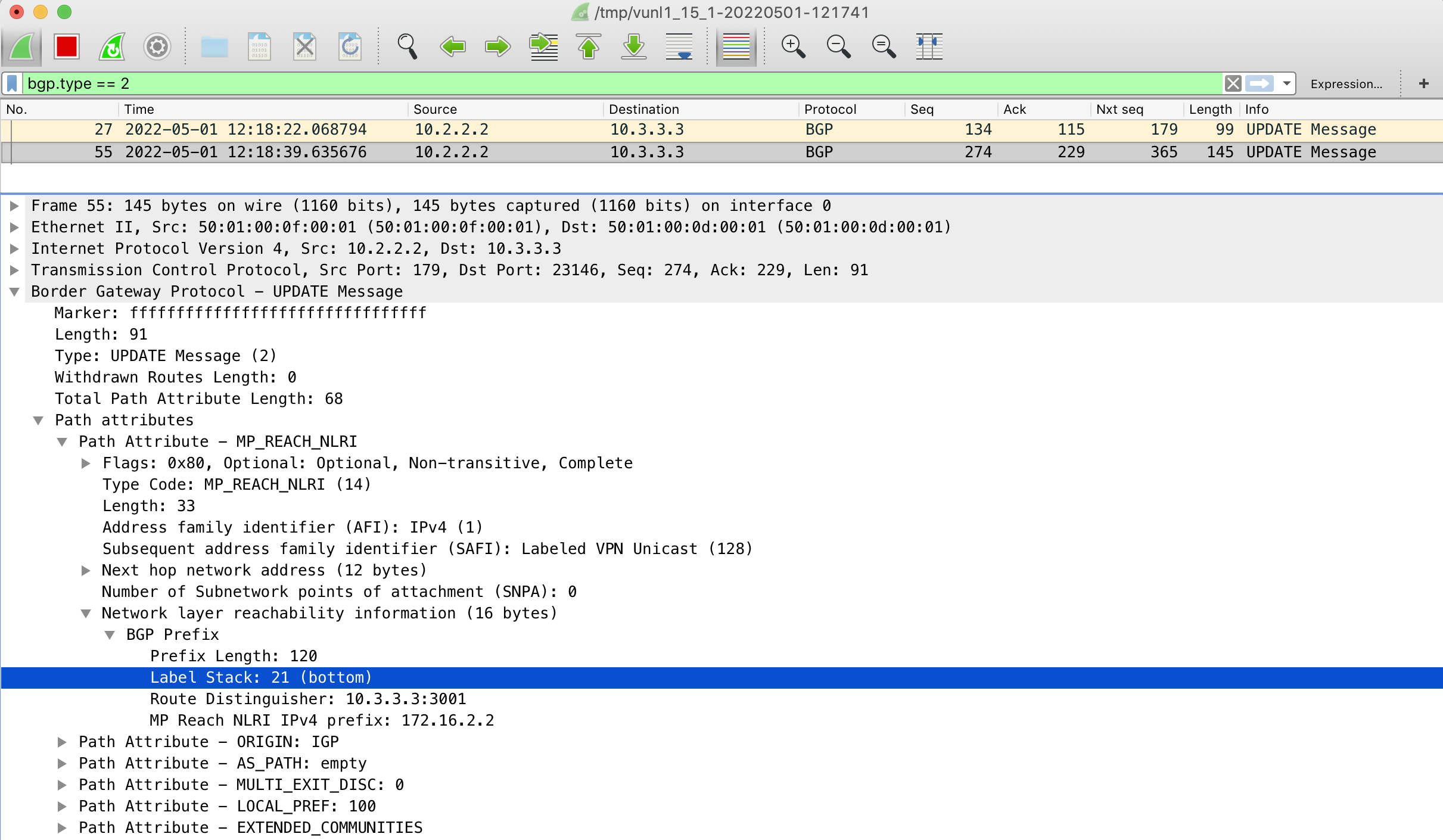
The below capture shows the BGP UPDATE message from WAN02 when loopback11 (172.16.2.2) was brought up. You can see in the BGP header that the BGP prefix holds an MPLS label (21) with bottom meaning it is to be Bottom-of-Stack (BoS).
The BGP assigned labels are either inner or outer labels and can be viewed per-prefix, per-rd, per-vrf or for all prefixes.
- inner label: Prefixes that the device is advertising, so the label a neighbor will use when sending packets through this device
- outer label: Prefixes learnt from a neighbor, so the label this device will use when sending packets through its neighbor
WAN02# show bgp vrf BLU 172.16.3.3
BGP routing table entry for 10.3.3.3:3001:172.16.3.3/32, version 14
Paths: (1 available, best #1, table BLU)
  Advertised to update-groups:
     2
  Refresh Epoch 2
  Local
    10.3.3.3 (via default) from 10.3.3.3 (10.3.3.3)
      Origin IGP, metric 0, localpref 100, valid, internal, best
      Extended Community: RT:65103:10003001
      mpls labels in/out nolabel/17
      rx pathid: 0, tx pathid: 0x0

WAN02# show bgp vpnv4 unicast all labels
   Network              Next Hop          In label/Out label
Route Distinguisher: 10.3.3.3:3001 (BLU)
   172.16.1.1/32        10.1.1.1          nolabel/17
   172.16.2.2/32        0.0.0.0           21/nolabel(BLU)
   172.16.3.3/32        10.3.3.3          nolabel/17
   172.16.100.1/32      10.1.1.1          nolabel/18
   172.16.100.2/32      10.1.1.1          nolabel/19
   172.16.100.3/32      10.1.1.1          nolabel/20
   172.16.200.1/32      192.168.200.1     16/nolabel
   172.16.200.2/32      192.168.200.1     18/nolabel
   172.16.200.3/32      192.168.200.1     19/nolabel
   192.168.100.0/30     10.1.1.1          nolabel/16
   192.168.200.0/30     192.168.200.1     20/nolabel
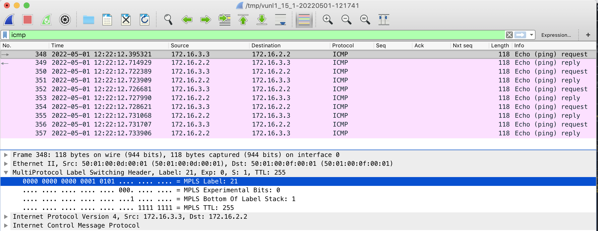
Traffic from CORE01 to Loopback11 (172.16.2.2) on WAN01 will use label 21, a ping sourced from loopback11 (172.16.3.3) is successful.
CORE01# show ip route vrf BLU 172.16.2.2
Routing Table: BLU
Routing entry for 172.16.2.2/32
  Known via "bgp 65103", distance 200, metric 0, type internal
  Last update from 10.2.2.2 00:24:43 ago
  Routing Descriptor Blocks:
  * 10.2.2.2 (default), from 10.2.2.2, 00:24:43 ago
      Route metric is 0, traffic share count is 1
      AS Hops 0
      MPLS label: 21
      MPLS Flags: MPLS Required

CORE01# show ip cef vrf BLU 172.16.2.2 detail
172.16.2.2/32, epoch 0, flags [rib defined all labels]
  recursive via 10.2.2.2 label 21()
    recursive via 192.168.112.1
      attached to GigabitEthernet2

CORE01# ping vrf BLU 172.16.2.2 source loopback 11
Type escape sequence to abort.
Sending 5, 100-byte ICMP Echos to 172.16.2.2, timeout is 2 seconds:
Packet sent with a source address of 172.16.3.3
!!!!!
Success rate is 100 percent (5/5), round-trip min/avg/max = 2/74/360 ms
This capture is taken on the link between WAN02 and CORE01 and shows the extra MPLS header with a label of 21. It has the BoS bit set indicating it is the last label in the stack causing WAN02 to forward it as an IP packet using the BLU routing table.
Labeled BGP peers must be adjacent
I configured the lab in this way with loopbacks thinking that if a WAN to CORE link went down it would route-through the problem. The idea was that a link between a WAN and the CORE01 went down the underlay peering would be lost (IPv4 BGP over physical interface) but the overlay peerings (VPNv4 BGP using loopback) would stay up as the loopback is routable via the other WAN.
WAN02(config)# int gi2
WAN02(config-if)# shut

CORE01#show ip bgp summary | in 19|N
Neighbor        V           AS MsgRcvd MsgSent   TblVer  InQ OutQ Up/Down  State/PfxRcd
192.168.111.1   4        65103     141     139        8    0    0 02:03:13        4
192.168.112.1   4        65103       0       0        1    0    0 00:00:31 Active

BGP router identifier 10.3.3.3, local AS number 65103
Neighbor        V           AS MsgRcvd MsgSent   TblVer  InQ OutQ Up/Down  State/PfxRcd
10.1.1.1        4        65103    2436    2434       33    0    0 02:04:16        5
10.2.2.2        4        65103    2436    2435       33    0    0 02:04:15        5

CORE01#show ip cef vrf BLU 172.16.2.2
172.16.2.2/32
  nexthop 10.2.2.2 GigabitEthernet2 label 21()
Although the CORE still has a route reachability between loopbacks on the CORE and WAN02 is broken.
CORE01#ping vrf BLU 172.16.2.2 source loopback 11
Type escape sequence to abort.
Sending 5, 100-byte ICMP Echos to 172.16.2.2, timeout is 2 seconds:
Packet sent with a source address of 172.16.3.3
.....
Success rate is 0 percent (0/5
From a packet capture I can see the packets arriving WAN01 but these are not forwarded onto WAN02. I think the reason for this is because when it gets to WAN01 it tries to forward it based on the label 21 but that label entry does not exist on WAN01.
WAN01#show mpls forwarding-table labels 21
Local      Outgoing   Prefix           Bytes Label   Outgoing   Next Hop
Label      Label      or Tunnel Id     Switched      interface
Goes to show you should read the RFC properly to start with, it states pretty clearly in there that this will not work.
- When the BGP Peers are not Directly Adjacent
Consider the following LSR topology: A–B–C–D. Suppose that D distributes a label L to A. In this topology, A cannot simply push L onto a packet’s label stack, and then send the resulting packet to B. D must be the only LSR that sees L at the top of the stack. Before sends the packet to B, it must push on another label, which was distributed by B. B must replace this label with yet another label, which was distributed by C. In other words, there must be an LSP between A and D. If there is no such LSP, A cannot make use of label L. This is true any time labels are distributed between non-adjacent LSRs, whether that distribution is done by BGP or by some other method.
Strangely although pings to loopback11 of WAN02 didn’t work, pings to loopback12 of DC2 did work.
CORE01#ping vrf BLU 172.16.200.2 source loopback 11
Type escape sequence to abort.
Sending 5, 100-byte ICMP Echos to 172.16.200.2, timeout is 2 seconds:
Packet sent with a source address of 172.16.3.3
!!!!!
Success rate is 100 percent (5/5), round-trip min/avg/max = 10/28/49 ms
The reason this worked was because the label used by 172.16.200.2 (18) exists on WAN01 for a different prefix (DC1 loopback11 172.16.100.1).
CORE01# show ip route vrf BLU 172.16.200.2
Routing Table: BLU
Routing entry for 172.16.200.2/32
  Known via "bgp 65103", distance 200, metric 0
  Tag 65102, type internal
  Last update from 10.2.2.2 01:07:19 ago
  Routing Descriptor Blocks:
  * 10.2.2.2 (default), from 10.2.2.2, 01:07:19 ago
      Route metric is 0, traffic share count is 1
      AS Hops 1
      Route tag 65102
      MPLS label: 18
      MPLS Flags: MPLS Required

WAN01# show mpls forwarding-table labels 18
Local      Outgoing   Prefix              Bytes Label   Outgoing     Next Hop
Label      Label      or Tunnel Id        Switched      interface
18         No Label   172.16.100.1/32[V]  1074          Gi3         192.168.100.1
Once traffic arrived at WAN01 it was IP forwarded into BLU VRF and after going round the houses eventually got to the destination.
CORE01# traceroute vrf BLU 172.16.200.2 source loopback 11
Type escape sequence to abort.
Tracing the route to 172.16.200.2
VRF info: (vrf in name/id, vrf out name/id)
  1 192.168.100.2 [MPLS: Label 18 Exp 0] 24 msec 13 msec 13 msec
  2 192.168.100.1 49 msec 21 msec 11 msec
  3 192.168.100.2 14 msec 15 msec 8 msec
  4 192.168.200.2 [MPLS: Label 18 Exp 0] 19 msec 14 msec 13 msec
  5 192.168.200.1 18 msec *  11 msec
Non-loopback overlay - Still doesn’t work
I tried changing the design to use the physical interfaces instead of loopbacks for the overlay peering to see if it made any difference.
WAN02# show ip bgp summary | in 651|N
BGP router identifier 10.2.2.2, local AS number 65103
Neighbor        V           AS MsgRcvd MsgSent   TblVer  InQ OutQ Up/Down  State/PfxRcd
192.168.110.1   4        65103      43      43        7    0    0 00:01:47        2
192.168.112.2   4        65103      40      44        7    0    0 00:01:50        2

WAN02# show bgp vpnv4 unicast all summary | in 651|N
BGP router identifier 10.2.2.2, local AS number 65103
Neighbor        V           AS MsgRcvd MsgSent   TblVer  InQ OutQ Up/Down  State/PfxRcd
192.168.110.1   4        65103      52      52       18    0    0 00:02:13        6
192.168.112.2   4        65103      49      53       18    0    0 00:02:16        1
192.168.200.1   4        65102      44      47       18    0    0 00:02:09        4
As expected with all the links up everything works the same as it did when using loopbacks for the overlay.
CORE01# show ip cef vrf BLU 172.16.200.1
172.16.200.1/32
  nexthop 192.168.112.1 GigabitEthernet2 label 21()

CORE01# traceroute vrf BLU 172.16.200.1 source loopback 11
Type escape sequence to abort.
Tracing the route to 172.16.200.1
VRF info: (vrf in name/id, vrf out name/id)
  1 192.168.200.2 [MPLS: Label 21 Exp 0] 10 msec 6 msec 8 msec
  2 192.168.200.1 5 msec *  9 msec

WAN02# show mpls forwarding-table labels 16
Local      Outgoing   Prefix              Bytes Label   Outgoing      Next Hop
Label      Label      or Tunnel Id        Switched      interface
16         No Label   172.16.200.2/32[V]  1140          Gi3           192.168.200.1
With the link between WAN02 to CORE01 down traffic must go through WAN01 and once again despite having the routing information traffic forwarding does not work as WAN01 has no entry for that label.
WAN02(config)# int gi 2
WAN02(config-if)# shut

CORE01#show ip cef vrf BLU 172.16.200.1
172.16.200.1/32
  nexthop 192.168.111.1 GigabitEthernet1 label 21()

CORE01#ping vrf BLU 172.16.200.1 source loopback 11
Type escape sequence to abort.
Sending 5, 100-byte ICMP Echos to 172.16.200.1, timeout is 2 seconds:
Packet sent with a source address of 172.16.3.3
.....
Success rate is 0 percent (0/5)

CORE01#traceroute vrf BLU 172.16.200.1 source loopback 11
Type escape sequence to abort.
Tracing the route to 172.16.200.1
VRF info: (vrf in name/id, vrf out name/id)
  1  *  *  *
  2  *  *  *
  3  *  *  *
  4
Summary
To sum up MPLS-VPN option B (InterAS option B)
- MPLS BGP forwarding is only supported on directly connected interfaces enabled to receive MPLS traffic (mpls bgp forwarding)
- The IPv4 BGP peering between devices is used to send and receive labels (send-label)
- It requires only one MP-BGP session (using physical interfaces or loopbacks) to exchange all VPN prefixes between the LSRs
- The MP-BGP session distributes labeled VPN prefixes between the LSRs. As a result, the traffic that flows between the LSRs is labeled
- Because the traffic is MPLS, QoS mechanisms that are applied only to IP traffic cannot be carried and the VRFs cannot be isolated
- This feature provides nonstop forwarding (NSF) and Graceful Restart
MPLS-VPN option B is pretty simple to setup and as long as you understand its limitations and use case it is a fairly straight forward to use and troubleshoot. If you did want to use it for intra-AS traffic in place of LDP you could probably workaround the limitations using per-VRF peerings, redistribution from other routing protocols or possibly static label entires. However all of these options would add a level of complexity to the solution so I am not really sure that there is much benefit to them.
The main reason I am looking at it is because this is the only option supported by Cisco SD-WAN. I still need to test it fully with SD-WAN but don’t think it be a problem in this scenario as there will be no MPLS between SD-WAN cEdges. MPLS would be used from each SD-WAN cEdge to the Core, but between the cEdges SD-WAN uses OMP to share routing information and this will be redistributed into BGP on the cEdges. Therefore in theory you would not have the problem as a prefixes will have their own labels generated on each cEdge.
Reference Links
https://blog.ipspace.net/2014/11/handling-bottom-of-mpls-stack.html
https://datatracker.ietf.org/doc/html/rfc3107
https://lostintransit.se/2016/03/02/ccde-inter-as-l3-vpns
https://www.cisco.com/c/en/us/td/docs/switches/datacenter/sw/5_x/nx-os/mpls/configuration/guide/mpls_cg/mp_interas_optionb_lite.html